
Space rigid body centroid position detection method based on vision and inertia unit fusion

An inertial unit and detection method technology, applied in the testing of machines/structural components, static/dynamic balance testing, measuring devices, etc., can solve the problems of difficult identification of feature points and poor adaptability, and achieve improved robustness and accuracy The effect of high degree and high measurement accuracy

Active Publication Date: 2020-09-08
HEBEI UNIV OF TECH
View PDF11 Cites 1 Cited by
  • Summary
  • Abstract
  • Description
  • Claims
  • Application Information

AI Technical Summary

Problems solved by technology

[0004] Xie Tangtao from the School of Aerospace and Materials Engineering, National University of Defense Technology, and others proposed a method for identifying the centroid of space non-cooperative targets based on visual feature points. This method calculates the velocity information of feature points by visually measuring and matching feature points on space targets. And position information, and then bring it into the space rigid body velocity equation to solve, it can achieve better accuracy under good lighting conditions, but only using visual methods to measure is easily interfered by space stray light, under lighting conditions In the case of too bright or too dark, the identification of feature points is extremely difficult, so the adaptability of this method is poor

Method used


Image

  • Space rigid body centroid position detection method based on vision and inertia unit fusion
  • Space rigid body centroid position detection method based on vision and inertia unit fusion
  • Space rigid body centroid position detection method based on vision and inertia unit fusion

Examples


Embodiment Construction

[0052] Specific examples of the present invention are given below. The specific embodiments are only used to further describe the present invention in detail, and do not limit the protection scope of the claims of the present application.

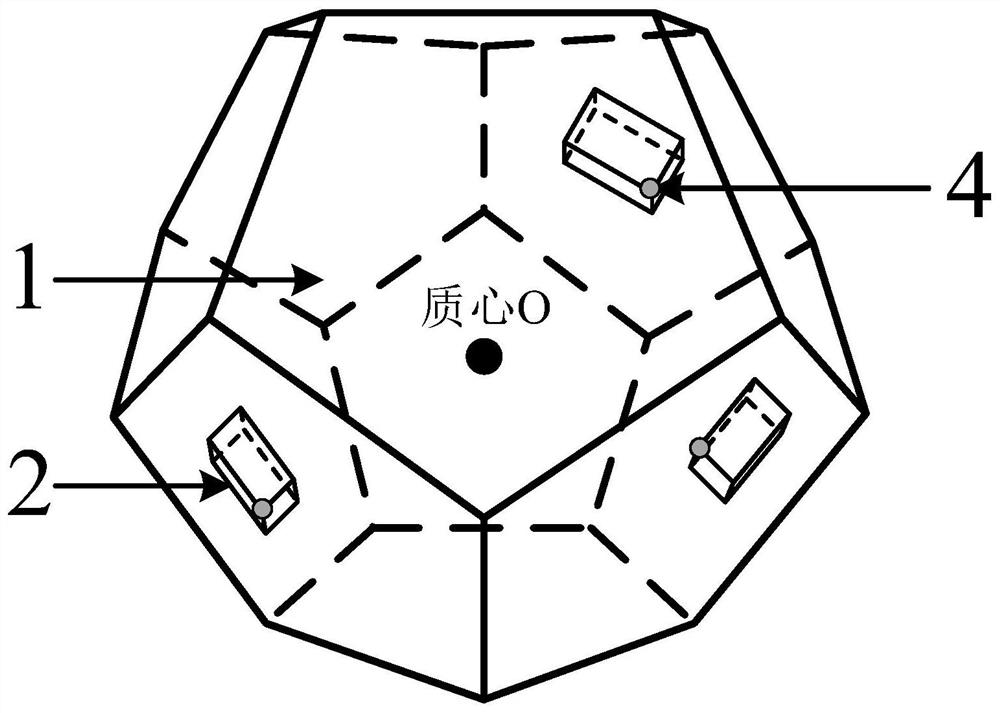
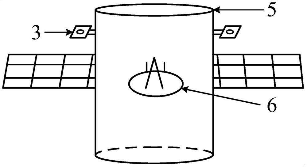
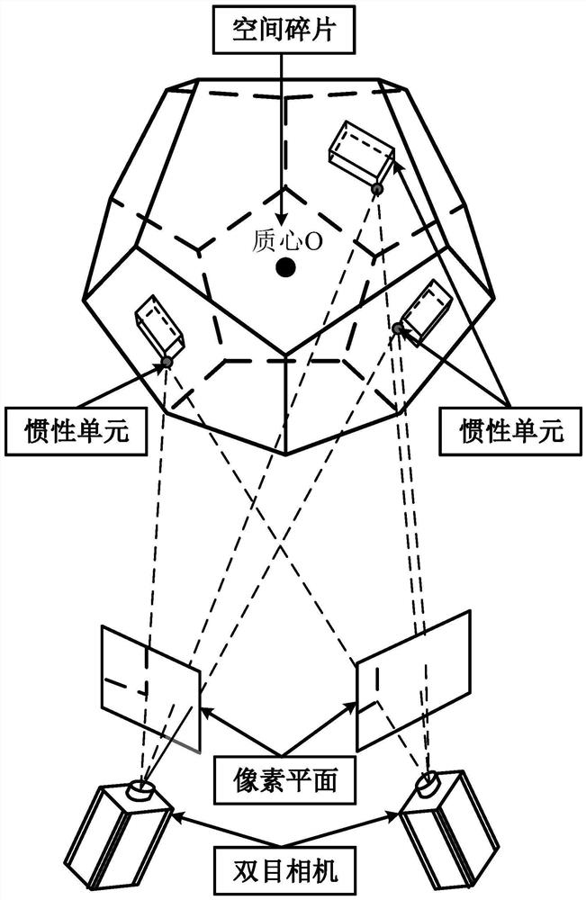
[0053] In the active removal process of space debris, the identification of the change of the center of mass of non-cooperative targets such as space debris, and the identification of the change of the center of mass of the cooperative target such as the derotation device satellite due to the process of extending the mechanical arm and the like, a space rigidity is proposed. The detection method of the position of the center of mass of the body, which can ensure the accuracy of the removal device for the selection of the derotation point of the space debris, and the stability of the derotation equipment after the derotation device is deployed, and ensure the correct execution of the removal device and the space debris in the derotation proce...


PUM


Abstract

The invention relates to a space rigid body centroid position detection method based on vision and inertia unit fusion. According to the detection method, a plurality of inertial units with light sources are arranged on a to-be-detected space rigid body, a mass center calculation module is included, and a plurality of radius measurement balls Ok are established with the positions hk of the inertial unit light sources as sphere centers and the distances rk between the positions of the inertial unit light sources and the mass center of the space rigid body as radiuses; finding out the shortest sum of distances from one point Qi in the space to each spherical surface by utilizing a plurality of established radius measuring balls Ok through a least square method correlation principle, and taking the coordinate of the point as the position of a centroid point measured at the moment i; continuously calculating the mass center positions at multiple moments, fusing the mass center positions atmultiple moments, continuously correcting the mass center positions, and when the error of the mass center positions at two moments is less than 5%, regarding the mass center positions as accurate positions. The method is designed for space rigid body centroid detection, visual and inertial units are fused, the advantages are complementary, and the robustness of the method is improved.

Description

technical field [0001] The invention relates to the technical field of centroid measurement of a rigid body in space, in particular to a detection method for measuring the centroid position of a rigid body in space. Background technique [0002] Since the Soviet Union launched the world's first artificial satellite "Spatnik 1" in the 1950s, humans have launched thousands of spacecraft, and the orbits around the earth have been occupied by millions of space rigid bodies. Covering, in order to determine the dynamic data of the space rigid body, firstly it is necessary to determine the center of mass data of the space rigid body. In space rigid bodies, apart from the small number and large-sized on-orbit equipment, the failed satellites, rocket final stages and collision derivatives have produced a large number of space debris with different sizes, especially. In March 2019, India conducted the country's first anti-satellite test, which used a three-stage missile to hit the In...

Claims


Application Information

Patent Timeline
Patent Type & Authority Applications(China)
IPC IPC(8): G06T7/70G01M1/12G06F17/11
CPCG01M1/122G06F17/11G06T7/70
Inventor 张慧博姚金铭赵宝山张跃戴士杰
Owner HEBEI UNIV OF TECH
Learn More