Energy storage management system and method based on B/S architecture, terminal and storage medium
A management system and S-architecture technology, applied in the field of energy storage management systems based on B/S architecture, can solve the problems of difficult to meet the needs of energy storage system users in remote areas, difficult distribution, poor compatibility, etc., to achieve good scalability, Extended functional range, easy maintenance effect
- Summary
- Abstract
- Description
- Claims
- Application Information
AI Technical Summary
Problems solved by technology
Method used
Image

Examples
Embodiment 1
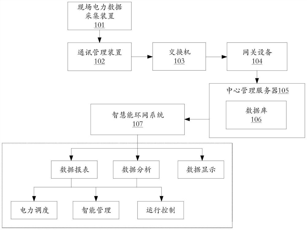
[0031] Such as figure 1 As shown, a schematic structural diagram of an energy storage management system based on a B / S architecture in an embodiment of the present invention is shown. The energy storage management system in this embodiment includes: on-site power data acquisition device 101 , communication management device 102 , switch 103 , gateway device 104 , central management server 105 , database 106 , and smart energy ring network system 107 .
[0032]The on-site power data acquisition device 101 is located at the site of the power environment (such as a power plant), and is used to collect on-site power data of the power environment, which can be analog output signals or digital output signals. These output signals include but are not limited to voltage data (phase voltage / Line voltage data), current data, frequency data, power factor data, electric energy data, battery data, etc.; battery data mainly includes battery cell information data (such as cell temperature d...
Embodiment 2
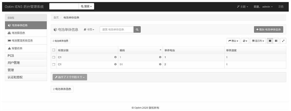
[0042] Such as figure 2 As shown in FIG. 1 , a schematic interface diagram of the energy storage management system based on the B / S architecture in an embodiment of the present invention is shown. In this embodiment, a web application platform is used as a B / S framework to display data required by an intelligent energy ring network system (IENS) through a database in the form of a browser.
[0043] In this embodiment, Django and Vue are selected as platform carriers for development. Django is a back-end framework under the python language system, and Vue is a front-end framework. Django development speed is fast, and Vue uses data-driven and component-based ideas to render Excellent performance. The pages developed by using Django and Vue as platform carriers are as follows: figure 2 shown.
[0044] exist figure 2 In the displayed page, the left column is the information catalog, and the right column is the specific information content. The information catalog in the l...
Embodiment 3
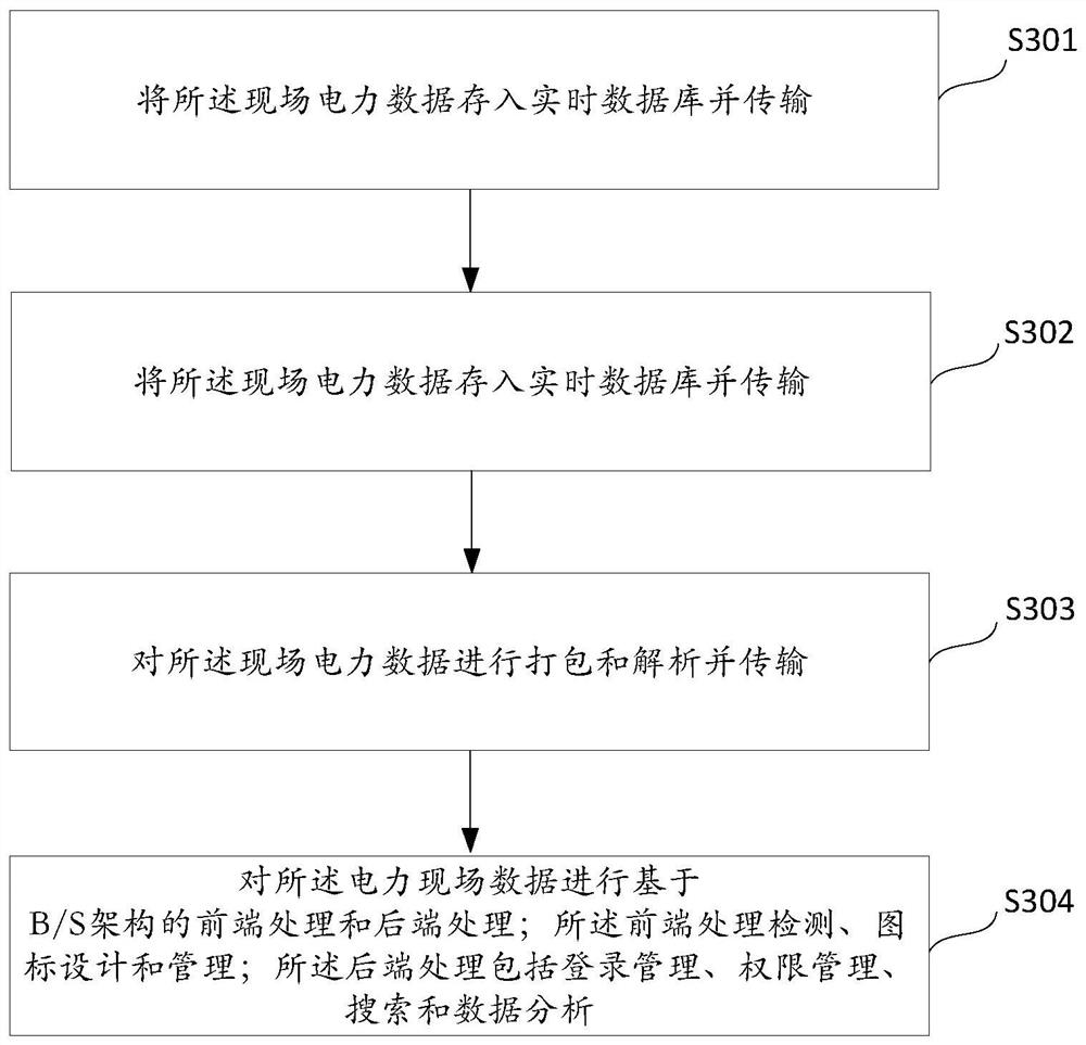
[0048] Such as image 3 As shown in FIG. 1 , it shows a schematic flowchart of a B / S architecture-based energy storage management method in an embodiment of the present invention. The energy storage management method in this embodiment includes steps S301-S304.
[0049] Step S301: Collect on-site power data of the power environment. The on-site power data includes but is not limited to voltage data (phase voltage / line voltage data), current data, frequency data, power factor data, electric energy data, battery data, etc.; where the battery data mainly includes battery cell information data (such as Cell temperature data, cell voltage data, coded information data, belonging cluster information data, etc.), battery cluster information data, alarm information data, etc.
[0050] Step S302: Store the on-site power data into a real-time database and transmit it.
[0051] Step S303: Packing, parsing and transmitting the on-site power data.
[0052] Step S304: Perform front-end p...
PUM
 Abstract
Description
Claims
Application Information
 - R&D
- Intellectual Property
- Life Sciences
- Materials
- Tech Scout
- Unparalleled Data Quality
- Higher Quality Content
- 60% Fewer Hallucinations
Browse by: Latest US Patents, China's latest patents, Technical Efficacy Thesaurus, Application Domain, Technology Topic, Popular Technical Reports.
© 2025 PatSnap. All rights reserved.Legal|Privacy policy|Modern Slavery Act Transparency Statement|Sitemap|About US| Contact US: help@patsnap.com