Manufacturing method for composite steel column of transition section of tower crown of super high-rise building

A production method and transition section technology are applied in the field of production of composite steel columns in the transition section of tower crowns of super high-rise buildings to achieve the effects of reducing butt joints, reducing welding seams and improving bearing capacity

Active Publication Date: 2020-09-11
中冶建工集团重庆建筑工业有限公司
View PDF8 Cites 4 Cited by
  • Summary
  • Abstract
  • Description
  • Claims
  • Application Information

AI Technical Summary

Problems solved by technology

Therefore, when the main body of the tower transitions to the tower crown, the outer frame steel column should be converted from the H-shaped section of the original rigid steel column to the diamond-shaped section structure. However, this type of section conversion has never been used in previous projects, and there is no reference. Therefore, How to realize the conversion of cross-section form and cross-section size has become a key problem in the production of steel columns in the transition section from the main structure of the tower to the crown structure.

Method used


Image

  • Manufacturing method for composite steel column of transition section of tower crown of super high-rise building
  • Manufacturing method for composite steel column of transition section of tower crown of super high-rise building
  • Manufacturing method for composite steel column of transition section of tower crown of super high-rise building

Examples


Embodiment Construction

[0026] The present invention will be described in further detail below in conjunction with the accompanying drawings and specific embodiments.

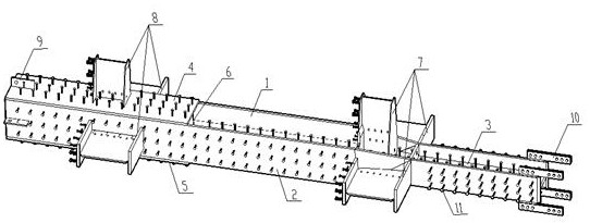
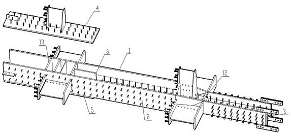
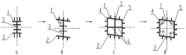
[0027] see figure 1 , figure 2 and image 3 , a combined steel column structure in the crown transition section of a super high-rise building, comprising a steel column and an upper corbel 8 and a lower corbel 7 arranged on the steel column, the upper corbel 8 and the lower corbel 7 have three corbels respectively The legs are used for one-to-one fixed connection with the corresponding three steel beams. The steel column is made of H-shaped steel made of long upper flange plate 1, lower flange plate 2 and web plate 3 and diamond-shaped cross-section The composite steel column composed of diamond-shaped steel columns includes, from bottom to top, an orthogonal H-shaped steel column section, a connecting H-shaped steel column section, an oblique H-shaped steel column section, and a diamond-shaped steel column section arranged above t...


PUM

PropertyMeasurementUnit
thicknessaaaaaaaaaa

Abstract

The invention discloses a manufacturing method for a composite steel column of a transition section of a tower crown of a super high-rise building. The composite steel column comprises a steel columnwhich is vertically arranged, upper brackets and lower brackets, wherein the upper brackets and the lower brackets are arranged on the steel column at intervals, and the steel column is sequentially composed of an orthogonal H-shaped steel column section, a connecting H-shaped steel column section, an oblique-crossing H-shaped steel column section and a rhombic steel column section from bottom totop; center lines of webs of the orthogonal H-shaped steel column section, the connecting H-shaped steel column section and the oblique-crossing H-shaped steel column section are located in the same straight line; the lower brackets are arranged on the connecting H-shaped steel column section; and a left flange plate and a right flange plate are correspondingly arranged between an upper flange plate and a lower flange plate of the upper end of the oblique-crossing H-shaped steel column section, the two sides of the left flange plate and the right flange plate are correspondingly and fixedly connected with the edge of the lower flange plate and the edge of the corresponding upper flange plate, so as to close the left and right sides of the upper flange plate and the lower flange plate, andan inclination angle of the rhombic steel column section corresponds to that of the tower crown. According to the manufactured composite steel column, the transition from the main structure of a towerbuilding to the tower crown structure can be effectively achieved.

Description

technical field [0001] The invention belongs to the field of building construction, and in particular relates to a method for manufacturing a combined steel column at the crown transition section of a super high-rise building. Background technique [0002] With the further development of super high-rise buildings, more and more super high-rise buildings need lateral force-resisting structural systems such as outer frame columns + core tubes + reinforced layer outrigger trusses to meet the structural design requirements. The main stress-bearing structural system of the outer frame column is usually a large-section combined steel column to ensure that the entire tower can exert its advantages in compression, torsion, and earthquake resistance under the action of gravity or external force. Corbels connected to the steel beams of each floor are arranged on the outer frame columns, and the corbels play a role in the stability of the connection between components to a large extent...

Claims


Application Information

Patent Timeline
Patent Type & Authority Applications(China)
IPC IPC(8): B23K9/00B23K9/173B23K9/18E04C3/32
CPCB23K9/0026B23K9/173B23K9/18E04C3/32
Inventor 郑会芬敬承钱谭孝平张望
Owner 中冶建工集团重庆建筑工业有限公司
Why Eureka
Try Eureka