
Eureka
For R&D, Eureka makes reading and utilizing patents & technical documents easy.
Eureka AIR
Designed for self-driven R&D workflows. Generate viable solutions, solve complex R&D challenges, empower your innovation with AI.

Eureka Materials
Designed for material experts only. Revolutionize your material R&D, from search, analyze, to developing new materials.

TechResearch
Generate reliable direction feasibility study reports for your R&D in just a few steps.

TechSeek
Discover and master advanced knowledge NOW. Basics, ideas, possibilities, all at once.

TechMind
As an expert in R&D Theories, TechMind can generates customized viable solutions instantly.

TechRisk
Analyze your overall solution with one click, know your potential R&D risks in advance.

TechMonitor
Get weekly tech updates, stay abreast of the latest tech innovations and key insights.
Optical device soft board welding tool
A technology for welding tooling and optical devices, which is applied in the direction of welding equipment, auxiliary welding equipment, welding/cutting auxiliary equipment, etc., can solve the problems of no uniform form and messy welding tooling for soft boards of optical devices, and achieve long service life and improved The effect of welding efficiency and welding quality, good versatility
- Summary
- Abstract
- Description
- Claims
- Application Information
AI Technical Summary
Problems solved by technology
Method used
Image

Examples
Embodiment 1
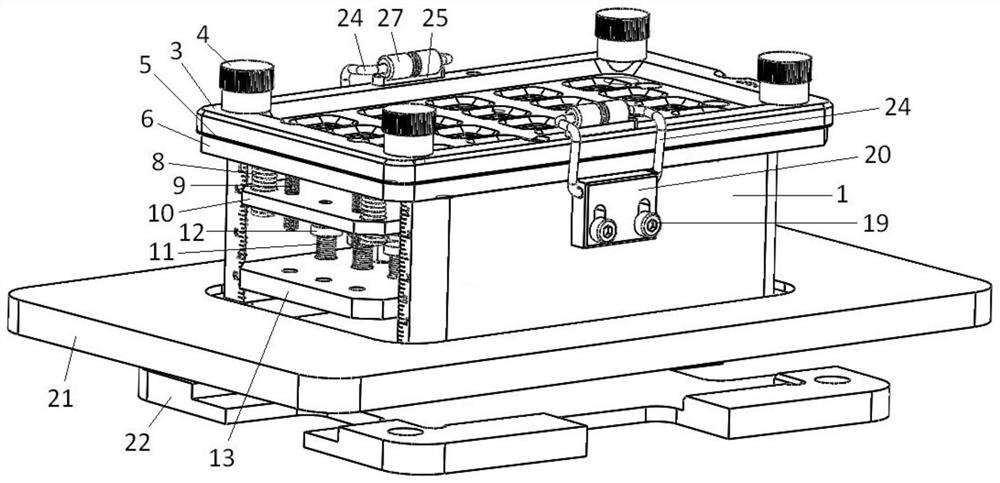
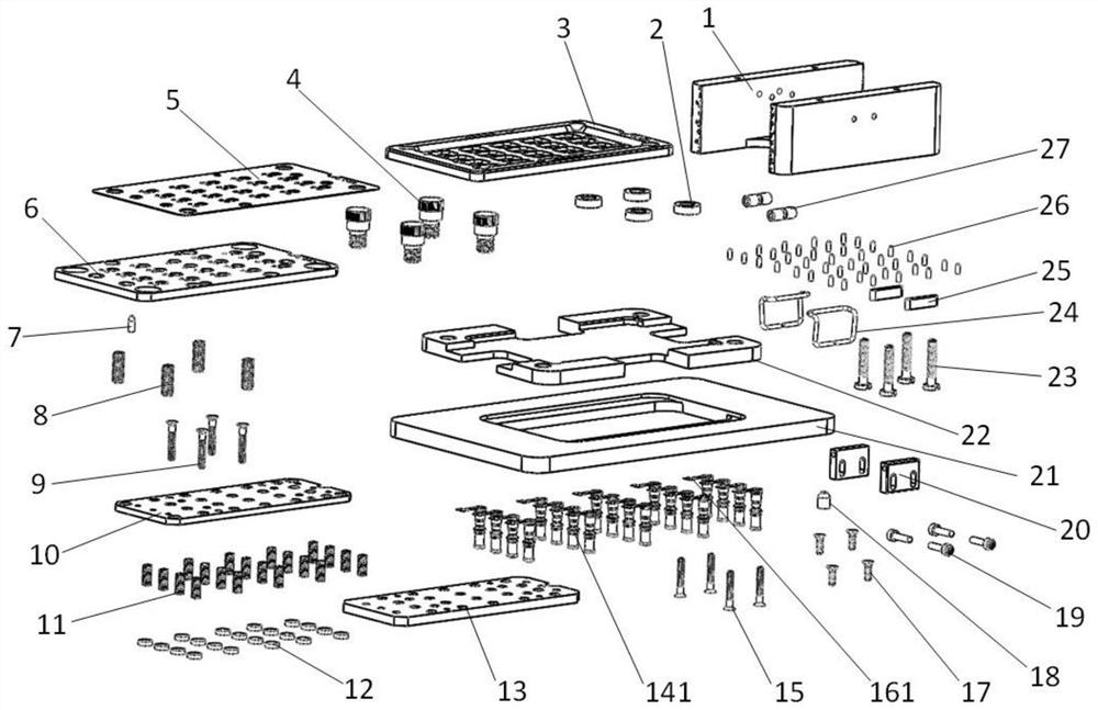
[0047] Such as Figure 1-Figure 3 As shown, an optical device soft board welding tool according to the present invention includes a base 1, a fixed support plate 6, an intermediate support plate 10, a bottom plate support plate 13, a soft board pressing sheet 5, an upper cover plate 3, an elastic member, Push piece, manual assembly seat 21 and automatic welding seat 22.
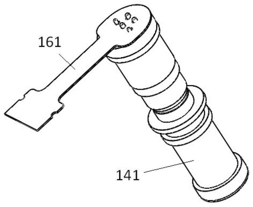
[0048] The fixed support plate 6 is an aluminum alloy member, the fixed support plate 6 and the base 1 are detachably connected by connecting countersunk screws 17 , and the fixed support plate 6 is used for the A-type device 141 to pass through.
[0049] The intermediate support plate 10 is parallel to the fixed support plate 6 and located at the lower part of the fixed support plate 6, the intermediate support plate 10 is used for the A-type device 141 to pass through, and can drive the A-type device 141 moves relative to the fixed support plate 6, so that the top surface of the A-type device 141 is flush ...
Embodiment 2
[0064] Such as Figure 4-Figure 6 As shown, the difference between the flexible board soldering tool for optical devices according to the present invention and the embodiment 1 is that the tooling in this embodiment is used for soldering the B-type device 142 and the B-type flexible board 162 .
[0065] The shape and size of the hole for the B-type device 142 to pass through on the fixed support plate 6 follow the shape, size and placement of the corresponding B-type device 142; The shape and size of the hole through which the B-type device 142 passes depends on the shape, size and placement of the corresponding B-type device 142; The shape and size of the first through hole follow the shape, size and placement of the corresponding B-type device 142; the first through hole for the B-type device 142 to pass through on the upper cover plate The shape and size of the corresponding B-type device 142 can be used for welding soft boards of BIDI series devices.
Embodiment 3
[0067] Such as Figure 7-Figure 9 As shown, the difference between the optical device flexible board welding tool of the present invention and the embodiment 2 is that the tool in this embodiment is used for welding the C-type device 143 and the C-type flexible board 163 .
[0068] Wherein, the C-type device 143 is substantially the same as the B-type device 142, and there are two surfaces to be welded on it, but embodiment 2 is aimed at one welding surface of the B-type device 142 and the B-type device 142. The soft board 162 is welded. In this embodiment, the other welding surface of the B-type device 142 is welded with the C-type soft board 163. Since the positions of the two welding surfaces of the B-type device 142 are different, the assembly The direction of clamping the B-type device 142 is different, so:
[0069] The shape and size of the hole for the C-type device 143 to pass through on the fixed support plate 6 follow the shape, size and placement of the correspondi...
PUM
 Abstract
Description
Claims
Application Information
 - R&D Engineer
- R&D Manager
- IP Professional
- Industry Leading Data Capabilities
- Powerful AI technology
- Patent DNA Extraction
Browse by: Latest US Patents, China's latest patents, Technical Efficacy Thesaurus, Application Domain, Technology Topic, Popular Technical Reports.
© 2024 PatSnap. All rights reserved.Legal|Privacy policy|Modern Slavery Act Transparency Statement|Sitemap|About US| Contact US: help@patsnap.com