
Liquefied air energy storage system

An energy storage system and liquefied air technology, applied in the field of energy and power, can solve problems such as unfavorable system frequency modulation performance and increase system response time, and achieve the effects of shortening response time, improving frequency modulation performance, and increasing liquefaction rate

Active Publication Date: 2020-09-11
GLOBAL ENERGY INTERCONNECTION RES INST CO LTD +2
View PDF4 Cites 10 Cited by
  • Summary
  • Abstract
  • Description
  • Claims
  • Application Information

AI Technical Summary

Problems solved by technology

[0004] When the turbine participates in the frequency modulation process, it is necessary to adjust the opening of the valve in front of the turbine to realize the change of output power, and the liquid air in the liquid tank needs to absorb heat and vaporize before expanding and doing work, which increases the response of the system during the frequency modulation process time, which is detrimental to the FM performance of the system

Method used


Image

  • Liquefied air energy storage system

Examples


Embodiment Construction

[0032] The technical solutions of the present invention will be clearly and completely described below in conjunction with the accompanying drawings. Apparently, the described embodiments are some of the embodiments of the present invention, but not all of them. Based on the embodiments of the present invention, all other embodiments obtained by persons of ordinary skill in the art without making creative efforts belong to the protection scope of the present invention.

[0033] In the description of the present invention, it should be noted that the terms "center", "upper", "lower", "left", "right", "vertical", "horizontal", "inner", "outer" etc. The indicated orientation or positional relationship is based on the orientation or positional relationship shown in the drawings, and is only for the convenience of describing the present invention and simplifying the description, rather than indicating or implying that the referred device or element must have a specific orientation, ...


PUM


Abstract

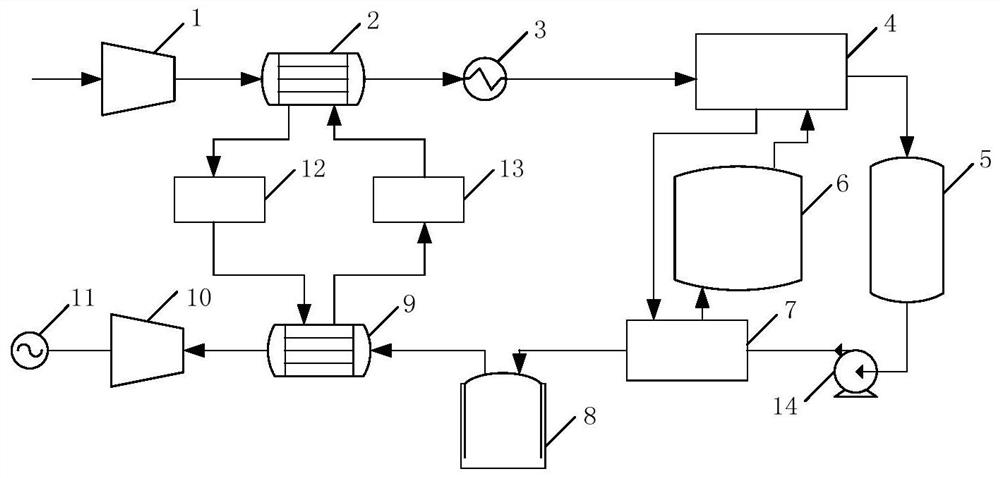
The invention discloses a liquefied air energy storage system. The liquefied air energy storage system comprises an energy storage unit, a liquidation unit, a liquid storage unit storing a liquid-state working medium, a gasification unit and an energy release unit, wherein the energy storage unit comprises a compression device, a first heat exchanger and a cooler which are sequentially connected;the energy release unit comprises an expansion unit and a second heat exchanger which are sequentially connected; the liquidation unit comprises a liquidation device with an inlet end which communicates with an outlet end of the cooler; the gasification unit comprises an evaporation device with an outlet end which communicates with an inlet end of the second heat exchanger; the liquid storage unitcomprises a liquid storage device connected between the liquidation unit and the evaporation device; a gas buffer device is further communicated between the evaporation device and the second heat exchanger; and a gas-state working medium generated in the evaporation device is temporarily stored in the gas buffer device and then enters the second heat exchanger. The gas buffer device is arranged between the evaporation device and the second heat exchanger, so that a response time in a process of adjusting output frequency of the liquefied air energy storage system can be shortened, and the frequency adjustment performance of the liquefied air energy storage system is improved.

Description

technical field [0001] The invention relates to the technical field of energy and power, in particular to a liquefied air energy storage system. Background technique [0002] The compressed air energy storage system is a large-scale energy storage system with air as the medium. It converts electric energy into potential energy storage of compressed air during the low peak of power consumption, and drives the turbine to do work through compressed air to release electric energy during the peak of power consumption. The liquefied air energy storage system is a new type of energy storage system proposed on the basis of compressed air energy storage. Compared with compressed air energy storage systems, liquid air energy storage systems have higher energy storage density, do not require large pressure storage containers, get rid of the constraints of geographical conditions, and have more advantages in development and application. [0003] Participating in power grid frequency re...

Claims


Application Information

Patent Timeline
Patent Type & Authority Applications(China)
IPC IPC(8): F01K11/00F01K25/08F01K25/10F01K15/00F28D15/02F28D20/02
CPCF01K11/00F01K25/08F01K25/10F01K15/00F28D15/02F28D20/02Y02E70/30
Inventor 徐桂芝白子为邓占锋梁丹曦宋洁彭笑东蔡林海
Owner GLOBAL ENERGY INTERCONNECTION RES INST CO LTD
Learn More