
Disassembling device and disassembling process for large-sized shielding main pump in radioactive environment

A radioactive and environmental technology, applied to the components, pumps, pump elements, etc. of the pumping device for elastic fluid, can solve the problems such as hindering the core pulling of the rotor assembly, and the lower radial bearing cannot be disassembled normally, and achieve the displacement deformation amount. Small, high precision and efficiency, stable structure

Active Publication Date: 2020-09-11
SANMEN NUCLEAR POWER CO LTD
View PDF7 Cites 4 Cited by
  • Summary
  • Abstract
  • Description
  • Claims
  • Application Information

AI Technical Summary

Problems solved by technology

Due to the small radial clearance between the lower radial bearing and the shielded main pump stator, the lower radial bearing cannot be disassembled normally after the bulge occurs
2. Core-pulling of the rotor assembly: After the shielding sleeve bulges, especially the bulging of the stator shielding sleeve between the lower radial bearing of the shielding main pump and the rotor winding, it seriously hinders the core-pulling of the rotor assembly, causing the rotor assembly to only Can be drawn out from the direction of the impeller, while the current rotor locking device is installed at the impeller end of the shielded main pump

Method used


Image

  • Disassembling device and disassembling process for large-sized shielding main pump in radioactive environment
  • Disassembling device and disassembling process for large-sized shielding main pump in radioactive environment
  • Disassembling device and disassembling process for large-sized shielding main pump in radioactive environment

Examples


Embodiment Construction

[0051] The present invention will be further described in detail below in conjunction with the accompanying drawings and specific embodiments.

[0052] A dismantling device for a large shielded main pump in a radioactive environment, including an impeller nut locking pin removal assembly, a C-shaped ring cutting assembly, a lower radial bearing disassembly, and a rotor core pulling assembly. in:

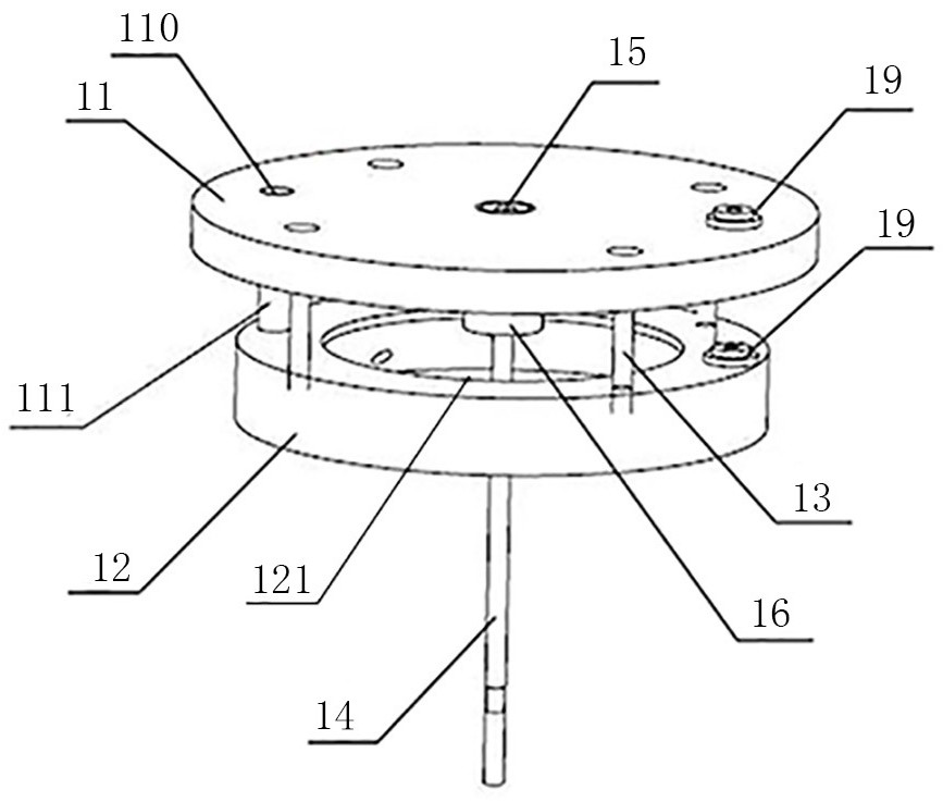
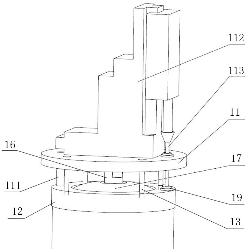
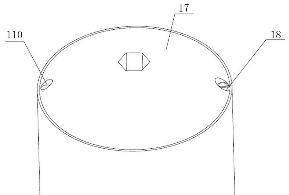
[0053] Such as Figure 1-3 As shown, the impeller nut locking pin removal assembly includes an upper plate 11, a lower plate 12, a connecting screw 13, a double-ended screw rod 14, a fixing nut 15, and an adjusting nut 16; the upper plate 11 and the lower plate 12 pass through the The connecting screw 13 is connected, and one end of the double-ended screw rod 14 is connected to the upper plate 11 through the fixing nut 15, and the other end passes through the lower plate 12 downwards, and is screwed to the impeller nut 17; the adjustment The nut 16 is arranged on the double-headed ...


PUM


Abstract

The invention discloses a disassembling device and a disassembling process for a large-sized shielding main pump in a radioactive environment, and belongs to the technical field of nuclear power station large-sized shielding main pump maintenance. The disassembling device comprises an impeller nut locking pin dismounting assembly, a C-shaped ring cutting assembly and a lower radial bearing dismounting and rotor core-pulling assembly, and the impeller nut locking pin dismounting assembly comprises an upper plate, a lower plate, a connecting screw, a double-end lead screw, a fixing nut and an adjusting nut; the C-shaped ring cutting assembly comprises a wall-mounted assembly and a cutting assembly; the wall-mounted assembly comprises a pressing plate and a wall-mounted main body; the lower radial bearing dismounting and rotor core-pulling assembly comprises a foundation plate, a foundation plate support used for connecting the foundation plate and a pump body, a double-end lead screw used for connecting the foundation plate and a lower radial bearing, a nut connected to the double-end lead screw and a lifting lug arranged on the foundation plate, a rotor supporting tool and a cushionblock which are used for connecting the foundation plate and a pump shaft, and a main bolt used for connecting the foundation plate and the pump body. The disassembling method is easy to operate, anddisassembling of the large-sized shielding main pump can be completed safely and efficiently.

Description

technical field [0001] The invention relates to the technical field of maintenance of a large-scale shielded main pump of a nuclear power plant, in particular to a dismantling device and a dismantling process of a large-scale shielded main pump in a radioactive environment. Background technique [0002] After the nuclear power plant has been in operation for a long time, the shielded reactor coolant pump (hereinafter referred to as: shielded main pump) thrust bearing, shielding sleeve and lower locking cup may have problems. Different from the dismantling process of the shielded main pump in the manufacturing plant, after the long-term operation of the shielded main pump of the nuclear power plant, the radioactive dose of the components in contact with the primary circuit medium is relatively high, so it is necessary to solve the disassembly of the shielded main pump components in a radioactive environment; and also need Solve the cutting of the C-type seal at the lower part...

Claims


Application Information

Patent Timeline
Patent Type & Authority Applications(China)
IPC IPC(8): F04D29/62B24B27/06
CPCB24B27/06B24B27/0616F04D29/628
Inventor 董宝泽王斌元李松李涛王信东耿加森廖长城曹阳郦元辉王扬王超林鑫辉杨志业
Owner SANMEN NUCLEAR POWER CO LTD
Learn More