
Material performance testing machine system in centrifugal force-high temperature coupling environment

A technology of material properties and centrifugal force, which is used in the analysis of materials, the use of stable tension/pressure to test the strength of materials, thermometers, etc. It can solve the problem that the performance testing device cannot perform high-throughput testing.

Pending Publication Date: 2020-09-11
ZHEJIANG UNIV
View PDF0 Cites 3 Cited by
  • Summary
  • Abstract
  • Description
  • Claims
  • Application Information

AI Technical Summary

Problems solved by technology

[0005] Aiming at the equipment problem that the high-speed rotating component performance test device cannot perform high-throughput testing, the present invention provides a test that is simple to assemble, easy to use, and has a high safety factor. A single test can realize simultaneous testing of multiple properties in a high-gravity environment. machine system

Method used


Image

  • Material performance testing machine system in centrifugal force-high temperature coupling environment
  • Material performance testing machine system in centrifugal force-high temperature coupling environment
  • Material performance testing machine system in centrifugal force-high temperature coupling environment

Examples


Embodiment Construction

[0083] The present invention will be further described below in conjunction with the accompanying drawings and specific implementation.

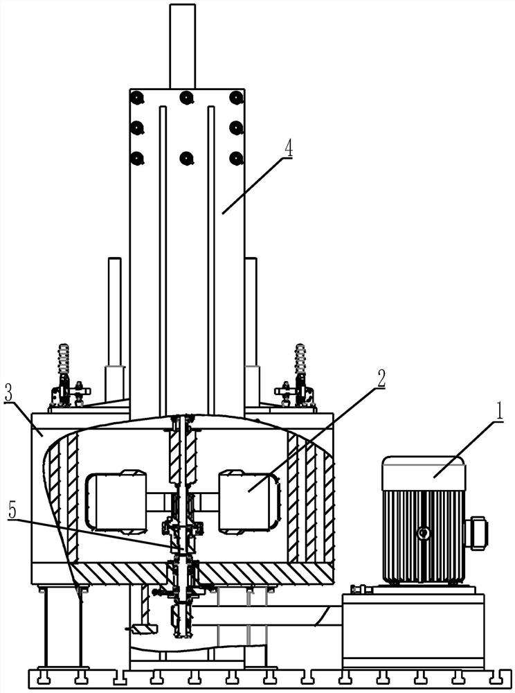
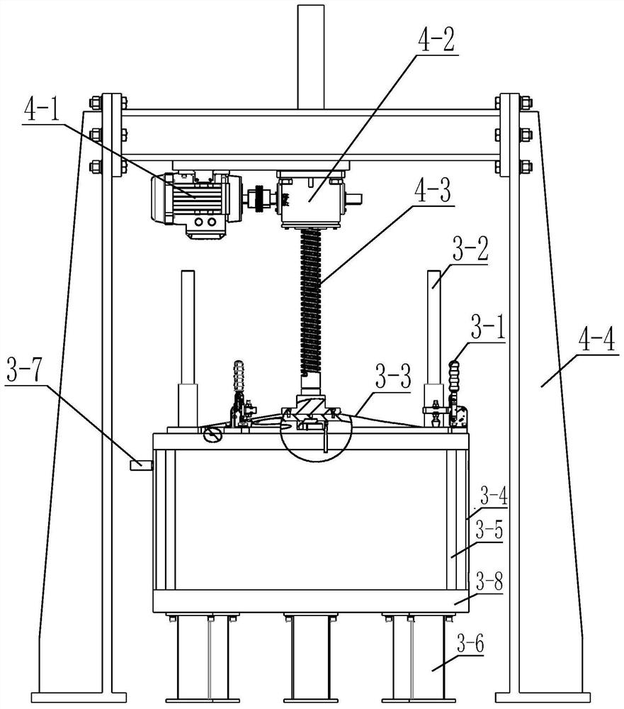
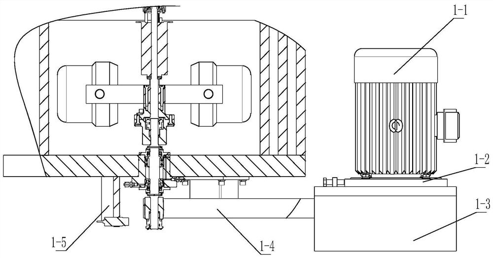
[0084] Such as figure 1 As shown, the specific implementation of the entire device includes a centrifugal host 1, a rotor system 2, an experimental chamber 3, a lifting system 4, and a down-driven spindle complex 5; the rotor system 2 and the down-driven spindle complex 5 are installed in the experimental chamber 3 , the bottom of the experimental chamber 3 is installed on the device base through a buffer structure, the centrifugal host 1 is installed on the device base at the side of the experimental chamber 3 and connected to the lower end of the down-driving spindle complex 5, and the upper end of the down-driving spindle complex 5 is connected to the rotor system 2, the lifting system 4 is installed on the base of the device and located above the experimental chamber 3, and the lifting system 4 is connected to the chamber cover of the e...


PUM


Abstract

The invention discloses a material performance testing machine system in a centrifugal force-high temperature coupling environment. A rotor system and a lower drive type main shaft complex are installed in the experiment cavity. The bottom of the experiment cavity is installed on the device base through a buffer structure, the centrifugal host is installed on the device base and connected with thelower end of the lower drive type main shaft complex, the lower drive type main shaft complex is connected with the rotor system, and the lifting system is installed on the device base, located abovethe experiment cavity and connected with the experiment cavity cover. A material performance testing system is installed in the hanging cup, the hanging cup is provided with a heat preservation device, the heat preservation device is provided with a heating device, the heating device is provided with a force bearing device, and the hanging cup is hinged to the end of a rotating arm of the supergravity centrifugal machine through a lifting lug. According to the invention, high-throughput testing of material properties such as durability, creep deformation, fatigue and the like in a centrifugalsupergravity environment is realized, and a uniform stress gradient, a non-uniform stress gradient, a uniform temperature field and a non-uniform temperature field can be applied to a sample so as tosimulate the working condition environment of the sample to the greatest extent.

Description

technical field [0001] The invention relates to a high-gravity material performance testing machine in the technical field of material performance testing, in particular to a material performance testing machine system in a centrifugal force-high temperature coupling environment. Background technique [0002] Blade machinery is key equipment in the aerospace, metallurgy, and energy industries, such as aero-engines, compressors, steam turbines, water turbines, etc. The design, operation, and maintenance of this type of machinery are related to the safety and stability of major engineering projects. Safety is of great importance. [0003] Turbine working blades, as the core components of aero-engine high-temperature gas work, are usually designed as geometric structures with variable cross-section, strong torsion (twist over 60 degrees), thin-walled curved surface (the thinnest part of the edge is less than 3mm), and complex topological shapes. The special geometric structure...

Claims


Application Information

Patent Timeline
Patent Type & Authority Applications(China)
IPC IPC(8): G01N3/18G01N3/02G01K7/02G01L1/22G01B7/16
CPCG01N3/18G01N3/02G01K7/02G01L1/2206G01B7/18G01N2203/0017G01N2203/0071G01N2203/0073G01N2203/0075G01N2203/0226G01N2203/0694G01N2203/0676G01N2203/0246
Inventor 韦华张泽陈云敏林伟岸
Owner ZHEJIANG UNIV
Learn More