Control system and method of intelligent flowerpot and intelligent flowerpot

A technology of intelligent flowerpot and control system, applied in the fields of botanical equipment and methods, container cultivation, gardening, etc., can solve the problems of complex wiring and low system reliability, avoid circuit short circuits, improve the degree of automation, and reduce labor costs Effect

Active Publication Date: 2020-09-15
TONGJI UNIV
View PDF8 Cites 5 Cited by
  • Summary
  • Abstract
  • Description
  • Claims
  • Application Information

AI Technical Summary

Problems solved by technology

[0005] In view of this, the present invention provides a control system for an intelligent flowerpot, an intelligent flowerpot and its control method for the problems that traditional flower maintenance relies on manual experience, the wiring of the existing potted flower system is compl

Method used


Image

  • Control system and method of intelligent flowerpot and intelligent flowerpot
  • Control system and method of intelligent flowerpot and intelligent flowerpot
  • Control system and method of intelligent flowerpot and intelligent flowerpot

Examples


Embodiment 1

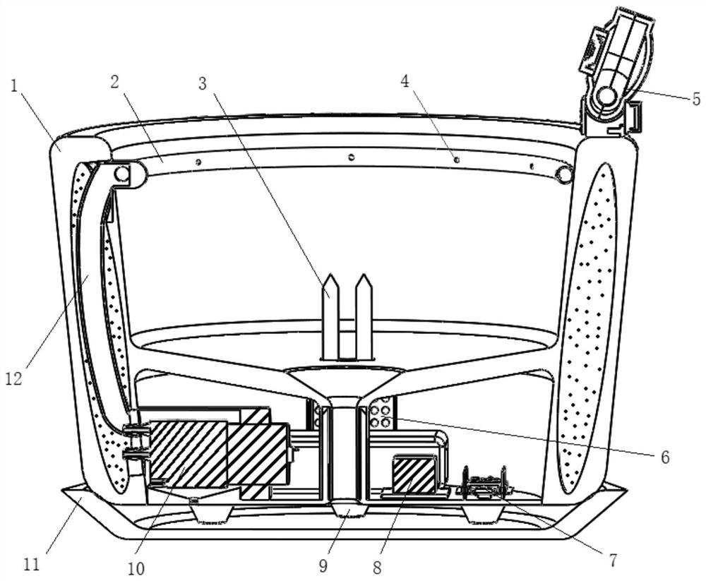
[0065] figure 1 It is a front view sectional structural schematic diagram of an intelligent flower pot in an embodiment of the present invention.

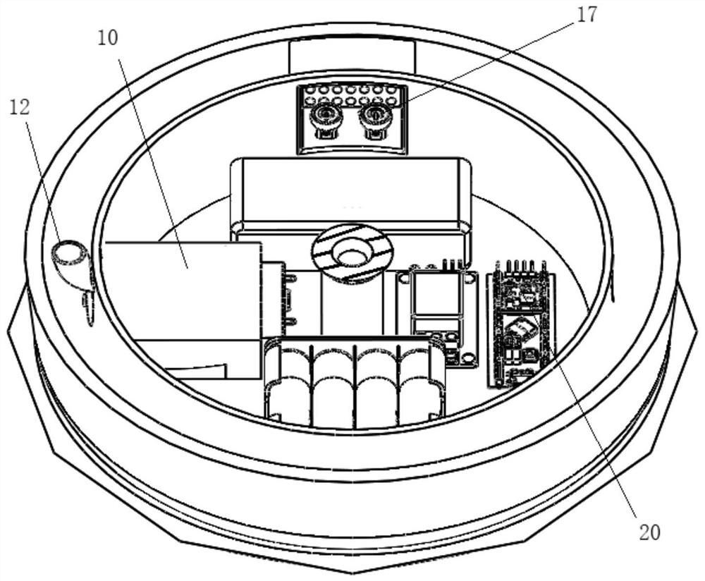
[0066] Such as figure 1 As shown, the smart flower pot includes a pot body 1, a clip 9 and a tray 11; it also includes an annular water pipe 2, an inner water pipe 12, a water pump assembly 10, a relay 8, a microcontroller assembly 7, a cooling plate 6, and a camera sensor Components 5 and soil temperature and humidity sensor 3 and other components. in:

[0067] The jacketed space inside the basin 1 is called the water storage chamber. Due to the design of the jacketed water storage chamber, it solves the problem that the working chamber occupies too much volume and has nowhere to place the water storage chamber; the basin 1 is upward The open semi-enclosed space is called the soil cavity; the closed space formed by the downwardly open semi-enclosed space of the basin body 1 and the upper surface of the clamp 9 is called the wor...
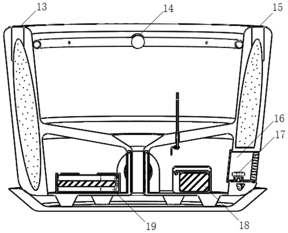
Embodiment 2

[0095] The second embodiment is similar to the first embodiment, the difference is that the first power supply 18 does not use a rechargeable 9V battery, and the second power supply 19 does not use a rechargeable four-cell 1.5V serial battery for power supply, but uses a single multi-gear Instead of a regulated power supply, because the voltage stability of the regulated power supply is improved, better watering effects, more accurate sensor values ​​and a more stable system working environment can be achieved. The cloud platform 36 is discarded, the camera 33 is embedded in the basin body 1, a probe-type water level sensor is arranged inside the water storage chamber, and the wiring extends from the interior of the basin body 1 to the working chamber. Integrating the air temperature and humidity sensor 34 and the light intensity sensor 35 with the cooling plate 6 is more conducive to simplification of wiring. Add an LCD screen arranged on the outside of the smart flower pot b...


PUM


Abstract

The invention discloses a control system and method of an intelligent flowerpot and the intelligent flowerpot. The control system comprises a sensor assembly and a control module. The sensor assemblyis used for acquiring image and environment data information and transmitting the image and environment data information to the control module; and the control module is used for receiving the image and environment data information through an input/output interface, processing the image and environment data information, and automatically starting and stopping a watering device according to a processing result. By the adoption of the system, the functions of flower growth environment data real-time acquisition, automatic watering and the like can be achieved, water and electricity separation ofthe flowerpot can be achieved, and the automation control degree is improved.

Description

technical field [0001] The invention relates to smart home application technology, in particular to a control system of a smart flowerpot, a smart flowerpot and a control method thereof. Background technique [0002] Potted plants can purify the air and cultivate sentiment, and are very popular in homes and offices. However, during the maintenance of flowers and green plants, the plants often wither due to lack of water, excessive watering, rotten roots and death, excessive light and yellow leaves and shrinkage, or even burn the plants due to excessive fertilization. [0003] The traditional extensive flower maintenance methods are difficult to guarantee the normal growth of flowers and plants. The widely used mechanical automatic watering device has a simple water supply method, which alleviates the problem of unmanned watering for a long time to a certain extent, but lacks effective monitoring of the parameters of the plant growth environment. [0004] The existing smart...

Claims


Application Information

Patent Timeline
IPC IPC(8): A01G9/02A01G27/02A01G27/00
CPCA01G9/02A01G27/003A01G27/02
Inventor 陈麒宇张志明
Owner TONGJI UNIV
Why Eureka
Try Eureka