Parallel X-ray CT imaging device

A CT imaging and X-ray technology, which is applied to measuring devices, material analysis using wave/particle radiation, instruments, etc., can solve problems such as inability to directly emit parallel rays, and lack of CT imaging detection devices, so as to shorten imaging time and improve Imaging resolution, the effect of improving detection efficiency

Pending Publication Date: 2020-09-15
CENT OF EXCELLENCE FOR ADVANCED MATERIALS +1
View PDF0 Cites 3 Cited by
  • Summary
  • Abstract
  • Description
  • Claims
  • Application Information

AI Technical Summary

Problems solved by technology

However, limited by the structure and emission principle of the X-ray tube itself, it cannot directly emit parallel rays
At present, there is no relevant CT imaging detection device

Method used


Image

  • Parallel X-ray CT imaging device
  • Parallel X-ray CT imaging device
  • Parallel X-ray CT imaging device

Examples


Embodiment Construction

[0032] Below, the present invention will be further described in conjunction with the accompanying drawings and specific implementation methods. It should be noted that, under the premise of not conflicting, the various embodiments described below or the technical features can be combined arbitrarily to form new embodiments. .

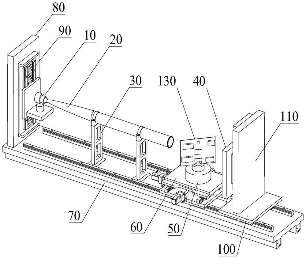
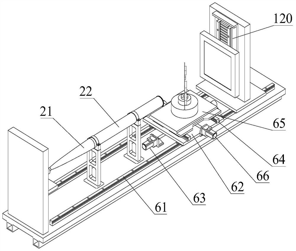
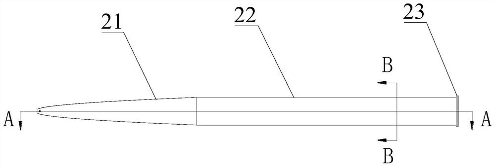
[0033] refer to Figure 1-Figure 2 , The present invention discloses a parallel X-ray CT imaging device, comprising: X-ray tube 10 , X-ray catheter 20 , catheter bracket 30 and high-precision detector 40 . Wherein, the X-ray tube 10 is used as a radiation source for emitting point-scattered X-rays. The X-ray conduit 20 is used to convert point-scattered light into parallel light. It includes a section of parabolic focusing conduit 21 and a section of linear conduit 22; 22 is cylindrical, and metal grid 221 is arranged inside (see Figure 3-Figure 5 ), specifically, the metal grid 221 includes a plurality of vertically arranged metal sheets and a plu...


PUM


Abstract

The invention discloses a parallel X-ray CT imaging device. The device comprises an X-ray tube, wherein the X-ray guide tube comprises a section of parabola focusing guide pipe and a section of linearguide pipe, a metal grid being arranged in the linear guide pipe; a guide tube bracket fixedly arranged at the bottom of the X-ray guide tube; and a high-precision detector used for receiving X-rays.The X-ray tube is arranged on one side of the parabola focusing guide tube, and a light source of the X-ray tube is located on the focus of the parabola where the parabola focusing guide tube is located. Point scattered light is reflected into parallel light; the imaging resolution is determined by the resolution of the detector instead of by the target focus size of the ray tube; and high imaging resolution can be achieved by adopting the high-precision detector, so that the high-power X-ray tube can be adopted as a ray source to penetrate through a thicker sample, the imaging time is shortened, and the detection efficiency is greatly improved.

Description

technical field [0001] The invention relates to the field of CT imaging, in particular to an X-ray CT imaging device. Background technique [0002] In order to solve the detection of small samples such as circuit boards and 3D printing complex components, it is usually necessary to use X-rays to perform high-precision CT imaging of key parts to obtain their internal structure and welding quality. [0003] Traditional industrial CT uses an X-ray tube as the radiation source, and the X-rays emitted by the X-ray tube penetrate the sample to be tested and reach the radiation detector, thereby realizing CT imaging. The quality of CT images will be affected by some performance indicators and parameters, such as resolution, noise, contrast and image trajectory, etc., and the spatial resolution will be affected by CT imaging geometric factors, one of which is the target focus of the ray tube size. [0004] The principle of traditional industrial CT determines that for an X-ray tub...

Claims


Application Information

Patent Timeline
Patent Type & Authority Applications(China)
IPC IPC(8): G01N23/046
CPCG01N23/046
Inventor 贡志锋马艳玲高建波张书彦詹霞王晨张鹏
Owner CENT OF EXCELLENCE FOR ADVANCED MATERIALS
Why Eureka
Try Eureka