
Photovoltaic solder strip and photovoltaic module

A technology of photovoltaic ribbons and ribbons, applied in photovoltaic power generation, electrical components, semiconductor devices, etc., can solve problems such as low uniformity and stability of coating thickness, reduced long-term reliability of components, and virtual soldering

Pending Publication Date: 2020-09-15
SUZHOU YOURBEST NEW TYPE MATERIALS
View PDF0 Cites 0 Cited by
  • Summary
  • Abstract
  • Description
  • Claims
  • Application Information

AI Technical Summary

Problems solved by technology

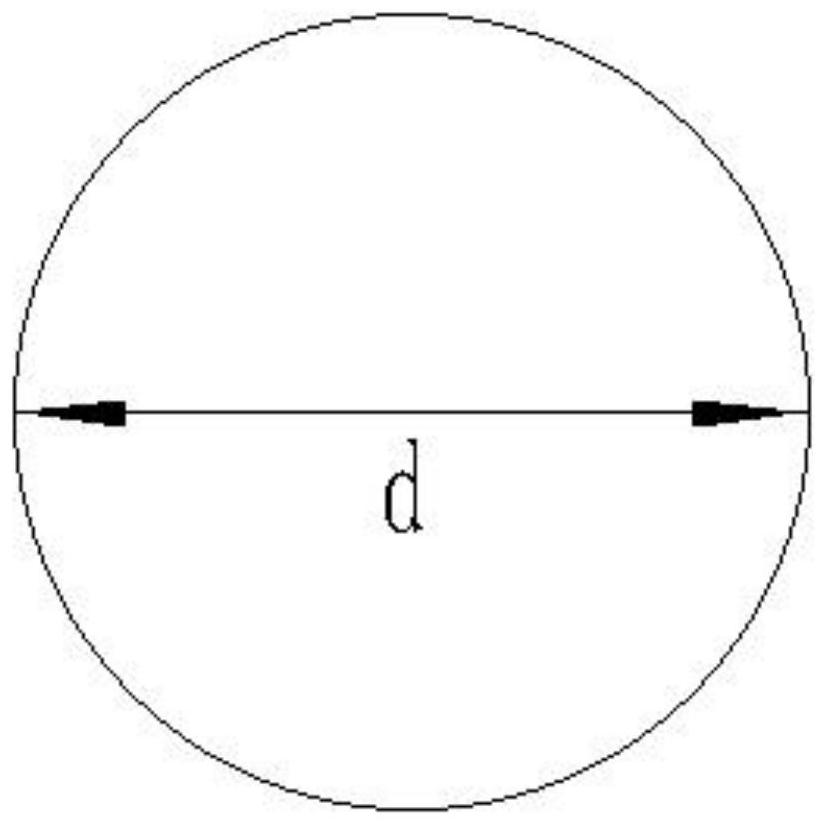
However, the conventional round copper substrate is thinner and has higher resistance, which leads to a certain loss of module power due to the higher resistance. If the diameter of the round ribbon is increased, the fragmentation rate of the battery and the hidden crack rate of the module will increase. Reduce the long-term reliability of the components and increase the manufacturing cost of the components
In addition, due to the small contact area when the round ribbon is welded with the cell, it is prone to defects such as virtual welding and low welding tension, and the process stability in the process of serial welding is not high enough.
Furthermore, due to the small surface tension of the circular copper substrate, the uniformity and stability of the coating thickness are not always high, which will lead to low welding tension after the ribbon is welded to the battery sheet

Method used


Image

  • Photovoltaic solder strip and photovoltaic module
  • Photovoltaic solder strip and photovoltaic module
  • Photovoltaic solder strip and photovoltaic module

Examples


Embodiment Construction

[0028] The technical solutions of the present invention will be further described below in conjunction with specific examples, but the present invention is not limited to these examples.

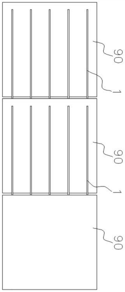
[0029] The technical solution of the present invention provides a photovoltaic ribbon, which includes a substrate and a coating coated on the outer surface of the substrate. The photovoltaic ribbon is a periodic ribbon section, and a single periodic ribbon section includes: the first Segments for bonding on front grid wires of photovoltaic cells, wherein the base of the first segment has a square cross-section or a square cross-section with rounded corners; and a second segment for connection and bonding adjacent photovoltaic cells.

[0030] By adopting a ribbon substrate with a square or rounded square cross section, the cross-sectional area of ​​the conductive substrate is increased without changing the width (or diameter) and thickness of the ribbon, and the resistance is reduced. Shaped...


PUM


Abstract

The invention provides a photovoltaic solder strip and a photovoltaic module. The photovoltaic solder strip comprises a base body and a coating which coats the outer surface of the base body, the photovoltaic solder strip is a periodic solder strip section, the single-period solder strip section comprises a first section body and a second section body, the first section body is used for being jointed on a front grid line of a photovoltaic battery piece, and the base body of the first section body is provided with a square cross section or a square cross section with fillets; and the second section body is used for connecting and jointing the adjacent photovoltaic cells. The photovoltaic module comprises at least two photovoltaic cells and the photovoltaic solder strip, and the at least twophotovoltaic cells are sequentially and adjacently arranged through the photovoltaic solder strip.

Description

technical field [0001] The invention relates to the field of photovoltaics, in particular to a photovoltaic ribbon and a photovoltaic module. Background technique [0002] Photovoltaic modules are used to convert solar energy into electrical energy. The photovoltaic modules include a plurality of photovoltaic cells, and two adjacent photovoltaic cells are connected in series by welding ribbons. The ribbon generally includes a ribbon base (or ribbon body) and a coating covering the outer surface of the ribbon base. In the early photovoltaic ribbons, the ribbon base often used a conductive substrate with a flat rectangular cross-section (such as a copper ribbon), but with the increase in the number of busbars on the photovoltaic cell, for example, the current multi-busbar battery Generally, there are more than 9 gate lines, and the corresponding busbar width is also narrower. Due to the large light-shielding area of ​​the traditional rectangular flat ribbon, the utilization ...

Claims


Application Information

Patent Timeline
Patent Type & Authority Applications(China)
IPC IPC(8): H01L31/05H01L31/0224H01L31/042
CPCH01L31/0508H01L31/0504H01L31/022425H01L31/042Y02E10/50
Inventor 肖锋
Owner SUZHOU YOURBEST NEW TYPE MATERIALS
Learn More