Oil application device for machining water heating hardware

A hardware and plumbing technology, applied in the field of oiling devices for plumbing hardware processing, can solve problems such as poor oiling effect, and achieve the effect of improving oiling effect and avoiding jamming.

Inactive Publication Date: 2020-09-18
烟台优正智能科技有限公司
View PDF0 Cites 0 Cited by
  • Summary
  • Abstract
  • Description
  • Claims
  • Application Information

AI Technical Summary

Problems solved by technology

[0004] Based on the technical problem of poor oiling effect of continuous feeding, spraying, and oiling of hardware in the prior art, the present invention proposes an oiling device for plumbing hardware processing

Method used


Image

  • Oil application device for machining water heating hardware
  • Oil application device for machining water heating hardware
  • Oil application device for machining water heating hardware

Examples


Embodiment 1

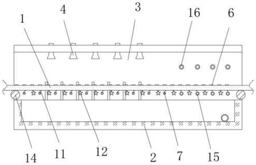
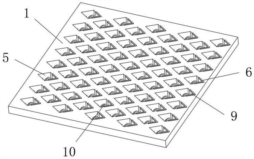
[0027] refer to Figure 1-4 , an oiling device for plumbing hardware processing, comprising a conveyor belt 1, a plurality of mesh holes 5 are provided on the top of the conveyor belt 1, a collection box 2 with an open top is provided at the bottom of the conveyor belt 1, and a collection box 2 on the top of the collection box 2 A fixed frame 3 is fixed between the two ends, and a plurality of nozzles 4 are fixed on the top of the fixed frame 3. The mesh 5 is arranged in a diamond-shaped structure, and the four water chestnuts of the mesh 5 are respectively arranged in the moving direction of the conveyor belt 1 and are perpendicular to each other. The two sides of the conveyor belt 1 are respectively set as the feed end and the discharge end, and the top of the conveyor belt 1 is located on the side of the mesh 5 near the discharge end, and a V-shaped spacer 6 is fixed on the side. The edge of the position corresponding to the hole 5 is suitable.

[0028] In the present inve...

Embodiment 2

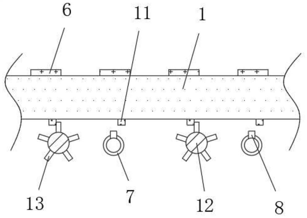
[0034] refer to Figure 1-5, an oiling device for plumbing hardware processing, the rotating part 12 is arranged as a tubular structure with one end open, and the middle position of the toggle part 13 is provided with an air chamber 13 communicating with the rotating part 12, the top of the air chamber 13 and The bottom end is penetratingly arranged, and the position corresponding to the opening of the rotating part 12 at one end of the fixing frame 3 is fixed with a positioning tube 17, and the outer wall of the positioning tube 17 is rotationally connected with the inner wall of the rotating part 12. For the air blower, the inner wall of the air chamber 18 away from the rotating part 12 is arranged in a conical structure that shrinks outwards, and the outer wall of the peripheral end of the toggle part 13 away from the rotating part 12 is arranged in an arc-shaped structure.

[0035] When in use, swing upward from the air cavity 18 to blow air, and the air flow passes throug...


PUM


Abstract

The invention belongs to the technical field of hardware machining, and particularly provides an oil application device for machining water heating hardware. By aiming at solving the problem of a pooroil application effect of continuous feeding and spray oil application on hardware in the prior art, the following scheme is proposed: the oil application device comprises a conveying belt, wherein multiple meshes are formed in the top of the conveying belt, a collecting box provided with an opening in the top is arranged at the bottom of the conveying belt, besides, a fixed bracket is fixed between two ends of the top of the collecting box, multiple spray nozzles are fixed to the top of the fixed bracket, the meshes are arranged in rhombus-shaped structures, four rhombus-shaped corners of each mesh are arranged in the moving direction and the perpendicular direction of the conveying belt respectively, and two sides of the conveying belt are set as a feeding end and a discharging end respectively. According to the oil application device, an oil circulating gap is formed between the hardware and the surface wall of the conveying belt, the sprayed oil on the conveying belt flows in alldirections due to collision with a separating piece under inertia to be contacted with the bottom of the hardware, and therefore, the actual oil application effect and completeness on the hardware bythe device are guaranteed.

Description

technical field [0001] The invention relates to the technical field of hardware processing, in particular to an oiling device for processing plumbing hardware. Background technique [0002] Plumbing hardware refers to the general term for hardware used in building water supply and drainage systems, heating systems and toilets, usually including faucets, showers, valves, pipe connectors and other hardware in toilets. Hardware processing is to use lathes and milling machines for raw materials , drilling machine, polishing and other machinery are processed into various parts according to the customer's drawings or samples, and oiling operations are often required during the processing of plumbing hardware. [0003] Nowadays, in the process of oiling plumbing hardware, generally the hardware is directly immersed in the oil for oiling operation, which cannot be operated continuously and will cause great damage to the oil. With the rapid development of automation technology, now ...

Claims


Application Information

Patent Timeline
IPC IPC(8): B05B13/02
CPCB05B13/0221B05B13/0278B05B13/0292
Inventor 韩亚君
Owner 烟台优正智能科技有限公司
Why Eureka
Try Eureka