Preformed armour rod hemispherical end forming tool bit and forming device applying tool bit
An end forming and pre-twisted wire technology is applied in the field of pre-twisted wire hemispherical end forming cutter heads, which can solve the problems of complex automation equipment design, potential corona hazards in products, and high maintenance costs, and achieve the maximum economic benefit of enterprises. The effect of shortening the processing and molding cycle, and no maintenance and maintenance costs
- Summary
- Abstract
- Description
- Claims
- Application Information
AI Technical Summary
Problems solved by technology
Method used
Image

Examples
Embodiment 1
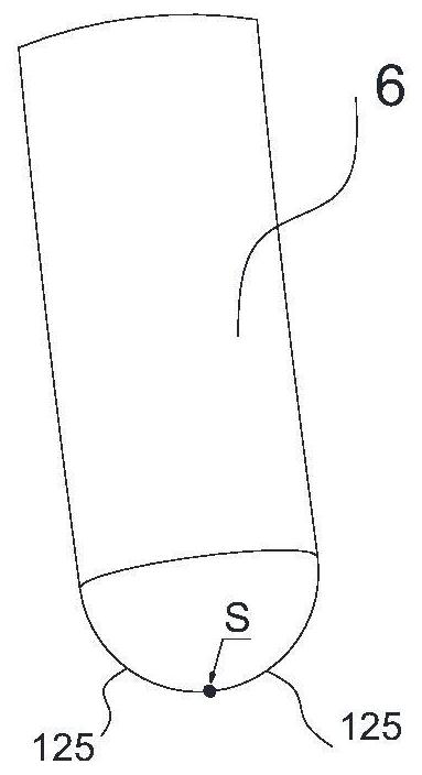
[0062] In this embodiment, the forming cutter head includes four identical metal strips 11 with a square cross-section; the four metal strips also have a regular shape after they are put together, which is beneficial for fastening and assembling the cutter head and the forming device. The end of each metal bar 11 is provided with a sub-cutter head 12, and the sub-cutter head 12 is formed by cutting and grinding the end of the metal bar 11; The blade 121 that is consistent with the meridian profile 125 of the part 2 is provided with a chip removal landslide 122 for chip removal from the blade 121 to the direction opposite to the blade 121, and each chip removal landslide is connected with the outside world after being assembled; four metal strips 11 Assembling to form the cutter head 1 with a square bottom, the lower apexes A of the blade profiles 123 of the four blades 121 are placed uniformly inward, and the four lower apexes A are focused together to form the pole S of the he...
Embodiment 2
[0065] This embodiment is basically the same as Embodiment 1, and the chip removal contour 124 is designed to be arc-shaped in this embodiment.
[0066] As attached in the manual Figure 4-Figure 10 As shown, the side on which the blade 121 is provided on the metal strip 11 is the blade surface 111, and the side opposite to the blade surface 111 is the chip removal surface 112; the chip removal surface 112 is provided with a chip removal profile 124, the chip removal profile 124 The height is lower than the edge profile 123 , and the uniform ratio of grinding and cutting from the edge profile 123 to the chip removal profile 124 forms a chip removal landslide 122 that communicates with the outside world. The contour shape of the chip removal contour in this embodiment may be the same contour shape as the blade contour, or may be an arc shape different from the blade contour shape. From the edge profile 123 to the arc-shaped chip removal profile 124 is a transitional molding wi...
Embodiment 3
[0068] As attached in the manual Figure 11-Figure 14 As shown, the present embodiment is a hemispherical end forming device for pre-twisted wire. In this embodiment, the cutter head described in Embodiment 1 or Embodiment 2 can be applied.
[0069] This embodiment mainly includes a workbench 2, a power unit 3, a clamping unit 4 and a guide unit 5;
[0070] The power unit 3, the clamping unit 4, and the guide unit 5 are all arranged on the workbench 2;
[0071] The rotating shaft 31 of the power unit 3 clamps the cutter head 1 through the clamping unit 4;
[0072] A guide unit 5 fixed on the workbench 2 is provided directly in front of the cutter head 1 .
[0073] Wherein, the power unit 3 is a three-phase asynchronous motor 32, and the motor 32 is fixedly arranged on the workbench 2 via fasteners. The clamping unit 4 includes a shaft sleeve 41. One end of the shaft sleeve 41 is fixedly socketed with the rotating shaft 31 through a fastener. In the cutter head receiving g...
PUM
 Abstract
Description
Claims
Application Information