Metal mold casting production line
A metal mold casting and production line technology, applied in foundry, casting equipment, metal processing equipment, etc., can solve the problems of high labor cost, ununiform process effect, and low consistency of casting quality.
Pending Publication Date: 2020-09-18
NINGGUO ZHICHENG MACHINERY MFG
0 Cites 0 Cited by
AI-Extracted Technical Summary
Problems solved by technology
[0003] The production method of traditional castings is time-consuming and labor-intensive, with high labor costs, and because e...
Method used
As above, the mold clamping or mold opening of casting machine 100 can be realized by controlling the relative action of lower mold base 132 and upper mold base 120, by controlling pouring machine 200 to move along the pouring line, and to the casting machine on the pouring line The mold 500 that has been clamped on 100 performs the liquid injection operation. In this way, the casting production line can realize the automatic operation of mold opening and mold closing of the mold 500, and use the pouring machine 200 to perform automatic liquid injection operation, which is different from the traditional method that only relies on Compared with manual casting, it greatly reduces the labor intensity and human influence factors, improves the efficiency of casting production and reduces labor costs, and at the same time improves the consistency of casting production quality.
During specific setting, the area of the cooling channel of patrix 510 corresponds to each patrix cavity 511, so that the cooling medium flowing into the cooling channel of patrix 510 can cool all patrix cavity 511 positions, The area of the cooling channel of the lower mold 520 is also corresponding to each lower mold cavity 521, so that the cooling medium flowing into the cooling channel of the lower mold 520 can cool all the positions of the lower mold cavity 521 to ensure that each cavity Cooling effect of inner castings.
For a casting machine 100, more than two stations can be set on its frame 110, and each station can be arranged in a straight line, so that each pouring station of the pouring line formed to facilitate the follow-up is all in a straight line On the one hand, it is convenient to control the movement and liquid injection operation of the pouring machine 200; meanwhile, the compactness of the structure can also be improved.
In this embodiment, also be provided with horizontal conveyer 700 below pouring line, the mold 500 of casting machine 100 is finished in liquid injection, and after carrying out relevant operation (later detailed description) to form casting, casting can also be cast The blanking operation is carried out to convey the formed castings to the horizontal conveyor 700, and the horizontal conveyor 700 conveys the castings formed by the casting machines 100 on the pouring line, which can further improve the automation of the casting production line.
In this embodiment, ...
Abstract
The invention discloses a metal mold casting production line comprising at least one pouring line and a pouring machine. The pouring line is provided with a plurality of casting machines. Each castingmachine is at least provided with a station for installing a mold. The mold comprises an upper mold seat for installing an upper mold of the mold, and a lower mold seat for installing a lower mold ofthe mold. The lower mold seat can vertically move relative to the upper mold seat so as to switch between a mold opening position and a mold combining position. The pouring machine can move along thepouring line so as to conduct liquid injection operation on the mold in the mold combining position on the corresponding casting machine. Through the metal mold casting production line, automatic production of mold opening and combining and pouring in casting manufacturing can be achieved, labor intensity of workers is lowered, human influence factors are reduced, casting production efficiency can be improved, labor cost can be lowered, and meanwhile consistency of casting production quality can be improved.
Application Domain
Casting plants
Technology Topic
EngineeringManufacturing line +6
Image
Examples
- Experimental program(1)
Example Embodiment
[0045] In order to enable those skilled in the art to better understand the solution of the present invention, the present invention will be further described in detail below with reference to the accompanying drawings and specific embodiments.
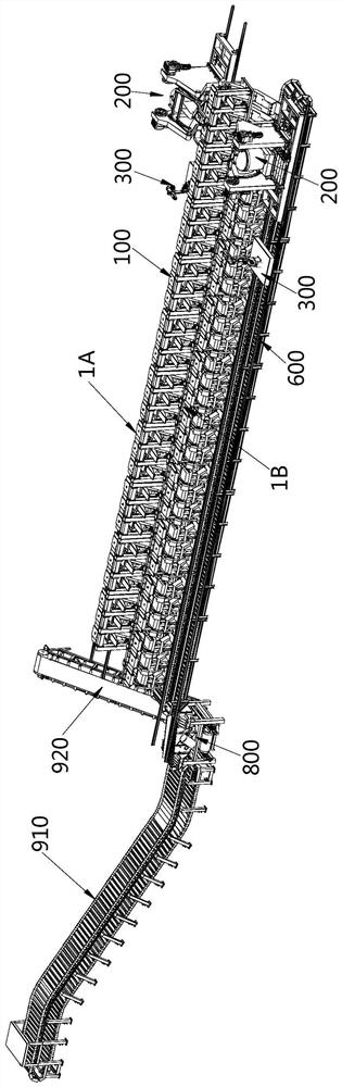
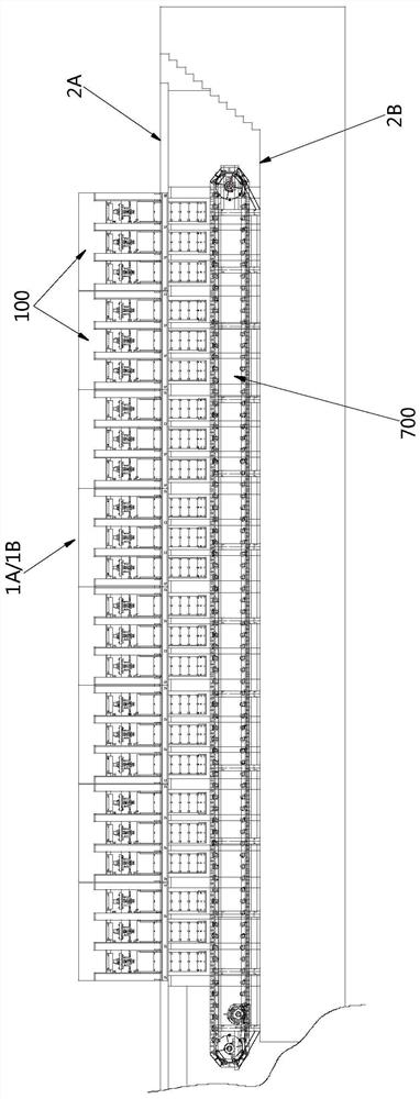
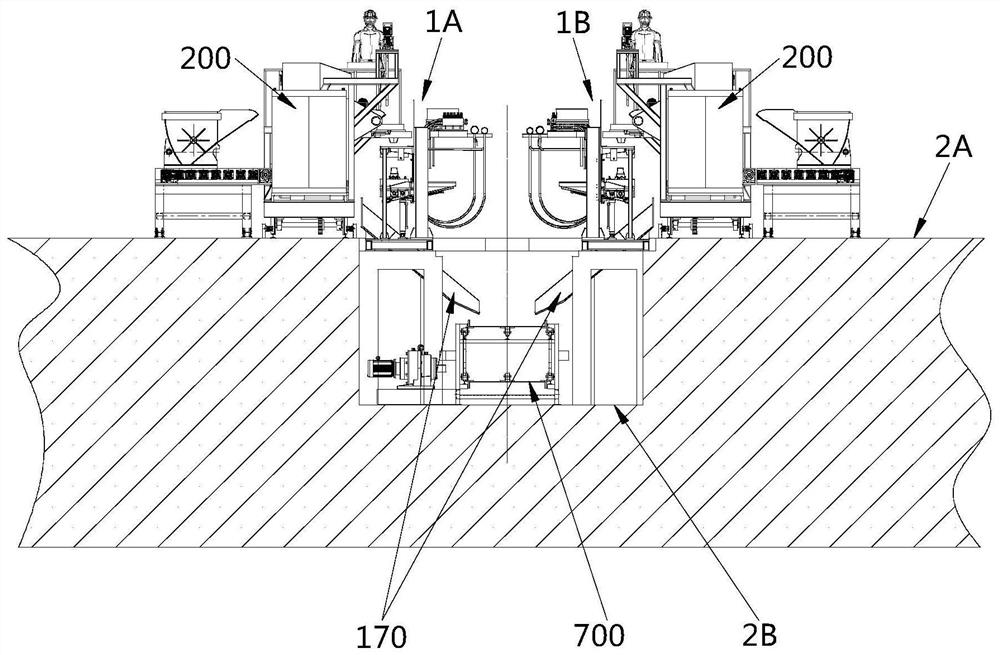
[0046] Please refer to Figure 1 to Figure 3 , figure 1 Is a perspective view of a specific embodiment of the metal mold casting production line provided by the present invention; figure 2 Is a side view of the pouring line of the metal mold casting production line in the specific embodiment; image 3 It is a schematic diagram of the end face of the metal mold casting production line in the specific embodiment.
[0047] The metal mold casting production line provided in this embodiment includes at least one pouring line and a pouring machine 200. There are multiple casting machines 100 on the pouring line. It is understood that the multiple casting machines 100 are arranged to form a pouring line.
[0048] Please refer to Figure 4 to Figure 6 , Figure 4 for figure 1 Axis side view of the middle casting machine; Figure 5 for Figure 4 Side view of the middle casting machine; Image 6 for Figure 4 The front view of the casting machine.
[0049] Each casting machine 100 has at least one station for installing the mold 500, which includes an upper mold seat 120 for installing the upper mold 510 of the mold 500 and a lower mold seat for installing the lower mold 520 of the mold 500 132. The lower mold base 132 is located below the upper mold base 120, wherein the lower mold base 132 can move vertically relative to the upper mold base 120 to switch between the mold opening position and the mold clamping position. It can be understood that, in the mold clamping position, the upper mold 510 and the lower mold 520 are attached to each other and are in a pouring state. In the mold opening position, the upper mold 510 and the lower mold 520 are separated.
[0050] The pouring machine 200 can move along the pouring line to perform liquid injection operation on the mold 500 in the clamping position on the casting machine 100.
[0051] As above, the mold clamping or mold opening of the casting machine 100 can be achieved by controlling the relative movement of the lower mold base 132 and the upper mold base 120, by controlling the pouring machine 200 to move along the pouring line, and controlling the casting machine 100 on the pouring line. The closed mold 500 performs the liquid injection operation. In this way, the casting production line can realize the automatic operation of opening and closing the mold 500, and the automatic injection operation using the pouring machine 200, unlike the traditional method that only relies on manual casting In comparison, the labor intensity of labor is greatly reduced, the human influence factors are reduced, the efficiency of casting production can be improved, the labor cost can be reduced, and the consistency of casting production quality can be improved.
[0052] Generally speaking, in order to facilitate the movement of the pouring machine 200 along the pouring line and the subsequent conveying operations for forming castings, the pouring line usually has a linear form, that is, multiple casting machines 100 are arranged in a straight line to form a pouring line. It is understood that the same pouring line The orientations of the casting machines 100 on the line are the same. In this way, when the casting machine 200 moves along the pouring line, it can directly perform the liquid injection operation on the mold 500 installed in each casting machine 100, regardless of the direction.
[0053] In a specific solution, the pouring machine 200 is driven by a driving unit to move along the pouring line. Specifically, a rail 600 is provided on the pouring side of the pouring line, and the pouring machine 200 can move along the rail 600 to the pouring line under the driving of the driving unit. The pouring station of the casting machine 100.
[0054] The pouring machine 200 specifically selects an automatic pouring machine and has a pouring control unit. The casting machine 100 includes a casting control unit, and the two are communicatively connected. The casting control unit of the casting machine 100 can control the mold clamping or mold opening of each station on it. , And feedback the clamping status of the upper station to the pouring control unit of the pouring machine 200. The pouring control unit can feed back the signal to the drive unit after receiving the signal that a certain station is already in the clamping position, so that the drive unit can drive It moves to the position to be poured in the mold clamping position, and performs liquid injection operation on the mold 500 of the mold clamping.
[0055] The pouring control unit is also used to control the automatic pouring operation of the pouring machine 200. Specifically, the pouring control unit can determine the pouring position and the pouring amount of the pouring port of the pouring machine 200 according to the load sensor and the visual sensor of the pouring machine 200. After the pouring is completed, the pouring completion signal can also be fed back to the casting control unit, so that the casting control unit controls the casting machine 100 to perform subsequent operations after the liquid pouring is completed.
[0056] What needs to be pointed out here is that in actual applications, the control programs of the above-mentioned control units can be designed with reference to existing control programs or based on the principles of existing control programs in combination with actual needs.
[0057] In the solution shown in the figure, two pouring lines are specifically provided, namely the first pouring line 1A and the second pouring line 1B, which are arranged in parallel, and the casting machine 100 of the first pouring line 1A and the second pouring line 1B The casting machine 100 is arranged backwards, so that when the casting machine 100 moves along the outside of each pouring line (one pouring line is away from the other pouring line), the casting machine 100 on the two pouring lines can be performed without changing the direction. Liquid injection operation. In other words, the pouring port of the casting machine 100 on the first pouring line 1A should be located on the side away from the second pouring line 1B, that is, on the outside.
[0058] In this embodiment, a horizontal conveyor 700 is also provided below the pouring line. After the mold 500 of the casting machine 100 is filled with liquid and related operations (described in detail later) are formed to form a casting, the casting can also be blanked In operation, the formed castings are transported to the horizontal conveyor 700, and the horizontal conveyor 700 transports the castings formed by the casting machines 100 on the pouring line, which can further improve the degree of automation of the casting production line.
[0059] On the basis of setting two pouring lines, the two pouring lines can share a horizontal conveyor 700, such as image 3 As shown, the horizontal conveyor 700 is located below the first pouring line 1A and the second pouring line 1B and between the first pouring line 1A and the second pouring line 1B. Obviously, the first pouring line 1A and the second pouring line 1B The blanking directions of the upper casting machine 100 are all toward the inside, so as to be close to the side between the two pouring lines.
[0060] As shown in the figure, each casting machine 100 on the pouring line is supported by the first supporting surface 2A, and the horizontal conveyor 700 is supported by the second supporting surface 2B. It can be understood that, in order to facilitate the blanking operation of the casting machine 100, the second supporting surface 2B Lower than the first supporting surface 2A.
[0061] In practical applications, the first supporting surface 2A is usually the ground, which is convenient for arrangement. In this way, the second supporting surface 2B is located under the ground, that is, it is necessary to dig down the corresponding position on the ground to facilitate the horizontal conveyor 700 and related components (after Text description) layout.
[0062] On this basis, in order to facilitate the transportation of the castings to the required position, a first lifting mechanism 910 is also provided at one end of the horizontal conveyor 700, and the castings on the horizontal conveyor 700 are lifted to the first lifting mechanism 910 through the first lifting mechanism 910. A supporting surface 2A, namely the ground, is convenient for subsequent transportation.
[0063] Specifically, the first lifting mechanism 910 may be an inclined slat conveyor, a bucket elevator, or other mechanisms with a lifting function.
[0064] Please refer to Figure 8 to Figure 10 , Figure 8 Is a schematic diagram of the structure of the upper mold of the mold in the specific embodiment; Picture 9 It is a schematic diagram of the structure of the lower mold of the mold and the sprue cup after assembly in the specific embodiment; Picture 10 It is a schematic diagram of the structure of the pouring cup in the specific embodiment.
[0065] In this embodiment, when pouring to form a casting, the pouring cup 400 is used to form the pouring port of the pouring liquid. Specifically, the pouring cup 400 is installed between the upper mold 510 and the lower mold 520, and the pouring machine 200 The sprue 411 of the sprue cup 400 is poured with molten metal, and flows into each cavity through the pouring channel inside the sprue cup 400 and the outlet 430 communicating with the pouring channel.
[0066] On this basis, the casting production line is also provided with a core setting robot 300 for placing the sprue cup 400 in the mold 500 installed at each station of the casting machine 100. The core setting robot 300 can move along the pouring line, specifically, The core setting robot 300 can move along the aforementioned track 600, that is, share the track 600 with the pouring machine 200.
[0067] The core setting robot 300 is also communicatively connected with the casting control unit of the casting machine 100 to feed back the placement state of the sprue cup 400 to the casting control unit, so as to facilitate the control of the casting machine 100 for subsequent operations.
[0068] In this way, the degree of automation of the casting production line can be further improved.
[0069] Please refer to Picture 12 , Picture 12 It is a schematic diagram of the structure of the core-setting robot in a specific embodiment.
[0070] In this embodiment, the core-setting robot 300 includes a mobile platform 310, a robot body 330, and a vision sensor 340. The mobile platform 310 can be matched with the rail 600 to facilitate the core-setting robot 300 to move along the rail 600.
[0071] In actual work, when the core-setting robot 300 moves to the station where the sprue cup 400 needs to be placed, its robot body 300 grabs the sprue cup 400 and then determines the position of the sprue cup 400 according to its vision sensor 340 to place the pouring cup 400 The beaker 400 is accurately placed on the lower mold 520 of the corresponding station.
[0072] In addition, a storage area 320 can be provided on the mobile platform 310 to store the pouring cup 400.
[0073] In actual installation, the visual sensor 340 can also be replaced by other sensors capable of positioning the placement position of the pouring cup 400.
[0074] Below Figure 8 to Figure 10 The solution shown exemplarily illustrates the structure of the mold 500 and the sprue cup 400. In actual applications, the mold 500 and the corresponding sprue cup 400 are also set differently according to the different casting structures.
[0075] In this embodiment, the mold 500 has multiple cavities to facilitate the one-time pouring of molten metal to cast multiple castings. The figure shows that each mold 500 has 5 cavities as an example. When actually set up, it can be There are more than 5 cavities, of course, it can also be 2 to 4 cavities.
[0076] Wherein, the upper mold 510 has 5 upper mold cavities 511, and the lower mold 520 has 5 lower mold cavities 512, respectively corresponding to the positions, so that after the upper mold 510 and the lower mold 520 are closed, the upper mold cavity 511 corresponds to The lower cavity 512 forms a cavity.
[0077] In order to facilitate the arrangement of the pouring cup 400 and the pouring liquid can flow into the cavities at the same time during pouring, the cavities are evenly distributed along a circumference.
[0078] The sprue cup 400 is placed at the center of each cavity. The number of outlets 430 of the sprue cup 400 is the same as the number of cavities, and the positions after assembly correspond one-to-one.
[0079] Specifically, the lower mold 520 has an installation position for installing the sprue cup 400, and the upper mold 510 has a through hole portion 512 for inserting the sprue cup. In application, the core lowering robot 300 can be used to place the sprue cup 400 on the lower mold 520. In the installation position, in the process of clamping the lower mold 520 and the upper mold 510, the sprue cup 400 is inserted into the through hole 512 of the upper mold 510. After the mold is closed, the sprue 411 of the sprue cup 400 exposes the surface of the upper mold 510 to It is convenient for the subsequent pouring machine 200 to perform liquid injection operations.
[0080] In a specific solution, for the convenience of production, the sprue cup 400 is a split structure, including an upper sprue portion 410 and a lower sprue portion 420, and the two can be specifically fixed by a snapping method to avoid misalignment affecting pouring.
[0081] In the solution shown in the figure, a part of the outlet 430 of the sprue cup 400 is formed below the upper gate portion 410, and the other part is formed above the lower gate portion 420, and the upper gate portion 410 and the lower gate portion 420 are engaged After that, the upper and lower parts of the outlet 430 correspond to the connecting ports that connect the gate channel and the cavity of the sprue cup 400, so that the molten metal flowing in from the gate 411 can flow out from the respective outlets 430 to the corresponding Cavity.
[0082] In a specific solution, the sprue cup 400 is a sandy sprue cup. After the casting is completed and the mold is opened, the sprue cup 400 is blanked along with the casting. The sprue cup 400 is affected by the high temperature molten metal and adheres to the casting. It is also easy to disperse, and may be scattered and formed into fragments during the blanking process. In other words, the sprue cup 400 is a disposable product.
[0083] After blanking, the waste sand formed by the sprue cup 400 and the casting move together with the horizontal conveyor 700.
[0084] On this basis, at one end of the horizontal conveyor 700 where the first lifting mechanism 910 is arranged, there is also a vibrating sand shaker 800, which is located between the horizontal conveyor 700 and the first lifting mechanism 910, and the horizontal conveyor 700 The conveyed castings with waste sand are first conveyed to the vibratory shakeout machine 800, and the shakeout operation is performed on the vibratory shakeout machine 800 to make the waste sand bonded on the casting separate from the casting, and the separated casting can be shaken out with the vibration The hopper of the machine 800 slides down onto the first lifting mechanism 910.
[0085] The casting production line is also provided with a second lifting mechanism 920 matched with the vibrating sand shaker 800 to transport the separated waste sand to the first supporting surface 2A.
[0086] Among them, the second lifting mechanism 920 may specifically be a belt conveyor with an inclination angle, or a bucket elevator.
[0087] In actual installation, the horizontal conveyor 700, the first lifting mechanism 910, and the second lifting mechanism 920 also have independent control modules. Each control module can interact with the aforementioned control units via Ethernet to achieve full Automated operation of the production line.
[0088] In this embodiment, a cooling system is also provided. After the pouring machine 200 completes the liquid injection, a cooling operation is performed to obtain a solidified casting. A smoke blowing mechanism 160 can also be provided to spray carbon deposits on the surface of the cavity of the mold 500 to form a carbon deposit layer before casting, so as to facilitate demolding.
[0089] The smoke spraying mechanism 160 can also be automatically controlled to avoid manual painting of an isolation protective layer on the surface of the cavity of the mold 500 for easy demolding.
[0090] Among them, the cooling system needs to be combined with the relevant structural functions of the mold 500, specifically, such as Figure 8 with Picture 9 As shown, cooling channels are formed inside both the upper mold 510 and the lower mold 520, and the cooling medium inlet 531 and the cooling medium outlet 532 of the cooling channel are formed on the peripheral wall of the upper mold 510 and the peripheral wall of the lower mold 520.
[0091] The cooling system includes a cooling medium source and pipes connected between the cooling medium source and the cooling medium inlet 531 and the cooling medium outlet 532 of the upper mold 510, and the cooling medium inlet 531 and the cooling medium connected between the cooling medium source and the lower mold 520. In the pipelines between the outlets 532, each pipeline is provided with a flow valve group. Through the control of the cooling control unit, the cooling passage is opened when cooling is required, and the cooling flow can be controlled. The cooling control unit can also record the cooling time to ensure the casting quality Solidified state.
[0092] During specific setting, the area of the cooling channel of the upper mold 510 corresponds to each upper mold cavity 511, so that the cooling medium flowing into the cooling channel of the upper mold 510 can cool all the positions of the upper mold cavity 511, and the lower mold 520 The area of the cooling channel is also corresponding to the lower mold cavities 521, so that the cooling medium flowing into the cooling channel of the lower mold 520 can cool all the positions of the lower mold cavities 521 to ensure the castings in each cavity Cooling effect.
[0093] Among them, the cooling medium may specifically be water, compressed air or others.
[0094] In this solution, part of the pipes of the cooling system and the smoke blowing mechanism 160 are integrated on the aforementioned casting machine 100, so as to facilitate related operations on the mold 500 at each station of the casting machine 100. Of course, in actual installation, It can also be relatively independent of the casting machine 100.
[0095] The casting machine 100 integrated with the cooling pipeline and the smoke blowing mechanism 160 will be described in detail below.
[0096] Such as Figure 4 to Figure 6 As shown, in this embodiment, the casting machine 100 includes a frame 110 that includes a base 111, at least two front support columns 112 located on one side of the base 110, and at least two rear support columns 113 located on the other side of the base 110 To Figure 4 with Figure 5 In the orientation shown, the front refers to the side close to the left, and accordingly, the rear refers to the side close to the right.
[0097] In the specific arrangement, the number of the front support columns 112 and the rear support columns 113 are the same, and the positions are one-to-one corresponding, and a station is formed between two adjacent front support columns 112 and two corresponding rear support columns 113.
[0098] Each station is provided with an upper mold base 120 and a lower mold base 132. The upper mold base 120 is used to install the upper mold 510 of the mold 500, and the lower mold base 132 is used to install the lower mold 520 of the mold 500. 132 can move vertically relative to the upper mold base 120 to switch between the mold opening position and the mold closing position.
[0099] For a casting machine 100, more than two stations can be arranged on the frame 110, and each station can be arranged in a straight line, so as to facilitate the subsequent formation of the pouring line and the pouring stations on a straight line. The movement and liquid injection operation of the pouring machine 200 are controlled; at the same time, the compactness of the structure can be improved.
[0100] In the solution shown in the figure, there are four supporting columns corresponding to the front and the rear of the casting machine 100 respectively. In this way, a casting machine 100 has three stations.
[0101] In actual applications, the number of stations of the casting machine 100 is set according to needs.
[0102] In this embodiment, in order to reduce the driving structure, the position of the upper mold base 120 is relatively fixed, and the lower mold base 132 can move closer to or away from the upper mold base 120 in the vertical direction. In actual installation, if there is no other requirement, of course, the lower mold base 132 can be relatively fixed, and the upper mold base 120 can move closer to or away from the lower mold base 132 in the vertical direction.
[0103] Specifically, the upper mold base 120 is fixed to the upper end of the frame 110 relative to the base 111, and it can specifically be fixed to the front support column 112 and the rear support column 113 at corresponding positions.
[0104] It should be pointed out that the structure of the upper mold base 120 should be such that after the upper mold 510 is installed, its upper surface is exposed, so that after assembly, the gate 411 of the sprue cup 400 can be exposed for the pouring machine 200 to perform the liquid injection operation.
[0105] In this embodiment, since the upper mold base 120 and the frame 110 are relatively fixed, in actual installation, the upper mold base 120 corresponding to each station can be an integrated structure, for example, an integrated upper mold base is provided, and the upper mold base has The upper mold base 120 corresponding to the number of stations.
[0106] In this embodiment, the lower mold base 132 can move in the vertical direction. In order to make the actions of each workstation relatively independent, the lower mold base 132 corresponding to each workstation is independently set.
[0107] Specifically, the lower mold base 132 is vertically slidably connected with the front support column 112 and the rear support column of the corresponding station.
[0108] In this embodiment, the casting machine 100 is also provided with a turning mechanism, which can drive the lower mold 520 to turn over, so that the castings located in the lower mold 520 can be automatically blanked after the casting is completed and the mold is opened, so as to improve the degree of automation; On the casting production line, the casting can be blanked to the horizontal conveyor 700.
[0109] In order to allow castings to fall smoothly and accurately from the casting machine 100 to the horizontal conveyor 700, the casting machine 100 is also provided with a blanking part 170, which is arranged obliquely, and its upper receiving end is located below the lower mold base 132 , Its tilt direction is related to the direction of blanking.
[0110] Such as Figure 5 As shown, in this solution, the upper end of the blanking member 170 is located in front of the front support column 112 to ensure that the casting can enter the blanking member 170 when it is dropped, and the whole is inclined backward and downward with respect to the frame 110, so that the casting can fall by gravity. The tilt direction of the material part 170 automatically falls.
[0111] In the casting production line image 3 When the two pouring lines are shown, and the two pouring lines share a horizontal conveyor 700, the casting machine 100 on the first pouring line 1A and the casting machine 100 on the second pouring line 1B are set back to face, that is, the casting machine 100 The front support column 112 is located outside the corresponding pouring line, so that the pouring machine 200 can inject liquid into the mold 500 of each station at the periphery. After the blanking part 170 is set as above, the blanking part 170 makes the casting direction It is the inner side of the pouring line, that is, between the two pouring lines, so that two pouring lines can share a horizontal conveyor 700.
[0112] It can be understood that, in the actual setting, if the liquid injection operation of the pouring machine 200 is not affected, and the problem of the two pouring lines sharing the horizontal conveyor 700 is not involved, the inclination direction of the blanking member 170 can be set to other as required, such as side Tilt or tilt to the front, etc., depending on the specific requirements.
[0113] In a specific solution, the blanking part 170 is a trough-shaped blanking hopper structure, and two sides of the blanking hopper are provided with ribs to prevent the casting from separating from the blanking part 170. Specifically, the inclination of the part of the blanking component 170 close to the discharge end thereof is set to be small, so as to provide a buffer for the casting, so that it can smoothly blank the material to the horizontal conveyor 700.
[0114] In this embodiment, in order to realize the vertical movement and turning action of the lower mold 520, a lower mold base 130 is specifically provided at each station of the casting machine 100, and the lower mold base 130 includes a lower mold base 132 and a lower turning base 133, The lower turning base 133 is rotatably connected with the lower mold base 132. During installation, the lower mold 520 is specifically installed on the lower turning base 133, and the lower mold base 132 can move vertically, driving the lower turning base 133 and the lower mold 520 installed on it together Moving vertically, the lower turning base 133 can also rotate relative to the lower mold base 132, so that the lower mold 520 mounted on it can be turned over to drop the casting to the blanking part 170.
[0115] Specifically, a sliding block 131 is fixed on the lower mold base 132, a guide rail 1131 extending in the vertical direction is installed on the rear support column 113, and the lower mold base 132 is slidably fitted with the guide rail 1131 through the sliding block 131, the sliding block 131 and the guide rail 1131 The cooperation of, can provide guidance for the vertical movement of the lower mold base 132, and ensure the directionality of the lower mold base 132 driving the lower mold 520 to move.
[0116] In actual installation, the lower mold base 132 and the front support column 112 may also be provided with sliding blocks and guide rails that cooperate with each other, specifically, the lower mold base 132 can move smoothly and vertically.
[0117] The casting machine 100 also includes a first driving member for driving the lower mold base 132 to move vertically upwards or downwards. The first driving member can be specifically set as a mold clamping cylinder 140, and the lower mold base 132 is driven by the expansion and contraction of the mold clamping cylinder 140 Move vertically up or down vertically.
[0118] Specifically, the cylinder body of the mold clamping cylinder 140 is fixed to the base 111 of the frame 110, the telescopic rod is fixed to the lower mold base 132, and the telescopic rod of the mold clamping cylinder 140 drives the lower mold base 132 to move up vertically when the mold base 132 is extended. When the telescopic rod of the mold cylinder 140 is retracted, the lower mold base 132 is moved vertically downward.
[0119] A limit switch can be set on the upper mold base 120. When the mold clamping cylinder 140 drives the lower mold base 132 to move to the mold clamping position of the lower mold 520 and the upper mold 510, the limit switch can feed back instructions to make the mold clamping cylinder 140 Stop the action to avoid moving transition and cause collision loss of related parts. Of course, in the actual setting, the telescopic rod of the mold clamping cylinder 140 can also correspond to the mold clamping positions of the upper mold 510 and the lower mold 520 when the mold clamping cylinder 140 is fully extended, so that the setting of limit switches can be omitted.
[0120] The casting machine 100 further includes a second driving member for driving the lower turning base 133 to rotate relative to the lower mold base 132. It can be understood that the second driving member and the lower turning base 133 constitute the aforementioned turning mechanism.
[0121] Specifically, the lower turning base 133 and the lower mold base 132 can be rotatably connected by a rotating shaft 1331, and the rotation center line is parallel to the horizontal direction and parallel to the arrangement direction of the front support column 112, and the lower turning base 133 is supported forward when turning over The direction of the column 112 rotates downward, driving the lower film 520 to rotate together, so that the lower mold cavity 521 is turned from the opening upward to the opening downward, so that the casting formed in it can fall to the lower drop under the action of gravity. 料 parts 170.
[0122] The second driving part specifically selects the turning cylinder 150. The fixed end of the turning cylinder 150 is hinged with the lower mold base 130, and the telescopic end is hinged with the lower turning base 133. The telescopic end of the turning cylinder 150 drives the lower turning base 133 around its rotation axis 1331. Flip.
[0123] In the solution shown in the figure, the fixed end of the turning cylinder 150 is specifically hinged with the lower end of the mounting seat 134 (described below) of the lower mold base 130, and the telescopic end is hinged with the lower end of the lower turning seat 133, and is configured as the telescopic end of the turning cylinder 150 When extended, the lower mold 520 mounted on the lower turning base 133 is in a state where it can be closed with the upper mold 510. When the telescopic end of the turning cylinder 150 is retracted, the lower turning base 133 drives the lower mold 520 to turn over to a position where the material can be dropped. Material level. In practice, the specific arrangement form of the turning cylinder 150 may also be other.
[0124] In this embodiment, the frame 110 of the casting machine 100 is also equipped with related hydraulic pipelines connected to the clamping cylinder 140 and the turning cylinder 150 and hydraulic valve groups that control the actions of the cylinders, such as Figure 4 As shown, a mounting plate 114 can be fixedly attached to the top of the rear side of the frame 110 (that is, the side where the rear support column 113 is located) to install these pipelines and hydraulic valve groups. Similarly, the mounting plate 114 can also be installed at the same time as the aforementioned The part of the cooling medium pipeline 180 related to the cooling system makes the structure more compact.
[0125] In this embodiment, a detection switch 190 can also be provided on the upper mold base 120. After the casting is completed and the mold is opened, the detection switch 190 is used to detect whether there is a casting stuck on the upper mold 510, so as not to affect the subsequent casting of the blanking. And the pouring of the next cycle. In practical applications, if a casting stays on the upper mold 510, the detection switch 190 can feed back a signal to the casting control unit to send an alarm signal to remind the operator.
[0126] It can be understood that the hydraulic valve group that controls the action of each oil cylinder and the aforementioned limit switch and detection switch 190 may be communicatively connected with the casting control unit of the casting machine 100 to make corresponding actions according to received instructions.
[0127] In practical applications, the first driving part and the second driving part may not be in the form of oil cylinders, for example, air cylinders or other driving parts may be used.
[0128] In this embodiment, the aforementioned smoke blowing mechanism 160 is specifically installed on the lower mold base 130, and can be moved together with the lower mold base 130 so as to be adjusted in a proper position. The upper mold 510 on the mold base 120 simultaneously performs the operation of injecting carbon deposits.
[0129] Of course, in actual installation, the positions of the smoking mechanism 160 and the frame 110 can also be relatively fixed, so that the mold clamping cylinder 140 is required to drive the lower mold 520 to move to a suitable position, so that the smoking mechanism 160 can simultaneously align the upper mold 510 and the lower mold 520. Work on it.
[0130] Specifically, the lower mold base 130 also includes a mounting seat 134 fixed to the lower mold seat 132. The mounting seat 134 is mainly located on the rear side of the rear support column 113. The smoke blowing mechanism 160 is installed on the mounting seat 134 to prevent spraying. During the carbon deposition operation, the operation of other parts of the casting machine 100 is not affected.
[0131] Please refer to Picture 11 with Figure 11a , Picture 11 Is a schematic diagram of the structure of the smoking mechanism in the specific embodiment; Figure 11a for Picture 11 Partial enlarged view of center C.
[0132] In this embodiment, the smoking mechanism 160 includes a driving part 161, a mounting table 162, an air ring 163 and an ignition needle 164.
[0133] Wherein, the gas ring 163 and the ignition needle 164 are installed on the mounting table 162. The gas ring 163 has an air inlet 1631 for inflow of combustion medium, and the gas ring 163 is provided with a plurality of air holes 1632 along its circumference.
[0134] The driving part 161 is used to drive the mounting table 162 to move the air ring 163 to switch between the ignition position between the upper mold 510 and the lower mold 520 and the non-ignition position when exiting the upper mold 510 and the lower mold 520.
[0135] The ignition needle 164 can ignite the combustion medium at each air hole 1632 to form a carbon deposit layer for isolation in each upper cavity 511 of the upper mold 510 and each lower cavity 521 of the lower mold 520 to facilitate subsequent demolding . Obviously, the ignition operation of the ignition needle 164 is performed when the gas ring 163 is at the ignition position between the upper mold 510 and the lower mold 520.
[0136] To facilitate the layout, such as Picture 11 As shown, each gas hole 1632 of the gas ring 163 is opened on its upward surface, and the ignition needle 164 is specifically located above the gas ring 163. In order to simultaneously ignite the combustion medium at each gas hole 1632, the ignition needle 164 is preferably located in the middle of the gas ring 163 area.
[0137] During specific installation, the mounting table 162 is mounted on the mounting seat 134 of the lower mold base 130 through the support frame 165, and the mounting table 162 is slidably connected to the support frame 165. The sliding direction of the mounting table 162 can be set parallel to the front and rear direction of the frame 110, That is, the mounting table 162 can move relative to the support frame 165 to the front side of the frame 110 to drive the gas ring 163 and the ignition needle 164 on it to move together between the upper mold 510 and the lower mold 520, or relative to the support frame 165 toward the frame 110 The rear side moves to exit between the upper mold 510 and the lower mold 520 to avoid affecting subsequent operations.
[0138] Specifically, a slider portion 1621 may be provided on the mounting platform 162, a sliding rail 166 is mounted on the support frame 165, and the slider portion 1621 cooperates with the sliding rail 166 to guide the sliding of the mounting platform 162.
[0139] In this embodiment, the driving component 161 may specifically be a telescopic cylinder or an electric push rod, etc. The movable end of the driving component 161 is connected to the mounting base 162, and the fixed end thereof can be mounted on the mounting base 134 of the lower mold base 130 through the mounting frame 167.
[0140] In a specific solution, the combustion medium used by the smoking mechanism 160 is acetylene, and the combustion of acetylene in the air is insufficient combustion, so that a carbon deposit layer can be formed in the cavity of the mold 500. In practice, the combustion medium can also be other gases that can generate carbon deposits.
[0141] When specifically set, the number of air holes 1632 of the gas ring 163 is the same as the number of cavities of the mold 500, and when in the ignition position, it corresponds to the position of each cavity to ensure a carbon deposit layer formed on the wall of each cavity.
[0142] Such as Picture 11 As shown, the gas ring 163 is specifically formed by bending a tube, one end of which is sealed with a port, and the other port forms an air inlet 1631, which is connected to a gas source with combustion medium through a pipeline, and an on-off valve can be provided on the pipeline. The smoking mechanism 160 can also be provided with a smoking control unit to control the action of the driving component 161, the opening and closing of the on-off valve, and the ignition operation of the ignition needle 164.
[0143] The smoke blowing control unit may specifically communicate with the casting control unit to control the actions of related components of the smoke blowing mechanism 160 according to feedback instructions from the casting control unit. For example, when the casting control unit feeds back that the upper mold 510 and the lower mold 520 are in the spraying position, the start signal can be fed back to the smoke spraying control unit. After receiving the start signal, the smoke spraying control unit sequentially controls the driving component 161 to drive the mounting table 162 Move to the ignition position, open the on-off valve to allow the combustion medium to flow into the gas ring 163, and then ignite the ignition needle 164. After the subsequent smoke spraying is over, the reverse actions of the components are controlled in turn.
[0144] It should be noted here that the smoking position and the ignition position mentioned here are actually the same position, that is, at this position, the ignition needle 164 can ignite the incomplete combustion of the combustion medium to produce carbon deposits and spray to the surface of the cavity.
[0145] Please refer to Figure 7a to Figure 7e , Respectively show the structural schematic diagrams of the casting machine in the clamping position, the mold opening position, the turning position, the smoking position and the smoking state in the specific embodiment.
[0146] Such as Figure 7a As shown, the casting machine 100 is in the mold clamping position at this time, that is, the mold clamping cylinder 140 drives the lower mold base 132 to move up to the lower mold 520 mounted on it to fit the upper mold 510 mounted on the upper mold base 120. It is understandable that this At this time, the pouring cup 400 has been placed in the mold 500. At this position, the pouring machine 200 can perform the liquid injection operation.
[0147] Such as Figure 7b As shown, the casting machine 100 is in the mold opening position at this time, that is, the mold clamping cylinder 140 drives the lower mold base 132 to move down to a state where the lower mold 520 and the upper mold 510 are separated. Specifically, the telescopic rod of the mold clamping cylinder 140 is completely retracted . At this time, if the liquid has been injected and cooled, and the casting has solidified, then the lower turnover seat 133 with the lower mold 520 can be turned over by the control of the turnover cylinder 150 to Figure 7c The shown turning position makes the casting and the sprue cup 400 fall to the blanking part 170; at this time, if it is before the liquid injection, then the lower mold 520 can be driven to move up to the upper mold 510 through the control of the clamping cylinder 140. Fit, ie Figure 7a The clamping position.
[0148] Such as Figure 7d As shown, the casting machine 100 is in the smoke spray position at this time, that is, the relative position between the lower mold 520 and the upper mold 510 is adjusted through the mold clamping cylinder 140, so that the smoke spray mechanism 160 and the upper cavity 511 of the upper mold 510 and The relative positions between the lower mold cavities 521 of the lower mold 520 are suitable to ensure the effect of spraying the carbon deposit layer, Figure 7d , The upper mold 510 and the lower mold 520 are in the smoking position, but the gas ring 163 and the ignition needle 164 of the smoking mechanism 160 have not moved to the ignition position, such as Figure 7e As shown, at this time, the driving component 161 of the smoke blowing mechanism 160 has driven the mounting table 162 to the ignition position. After the ignition needle 164 has been ignited, it is in the state of spraying the carbon deposit layer.
[0149] The metal mold casting production line provided by the present invention has been introduced in detail above. Specific examples are used in this article to illustrate the principle and implementation of the present invention. The description of the above examples is only used to help understand the method and core idea of the present invention. It should be pointed out that for those of ordinary skill in the art, without departing from the principle of the present invention, several improvements and modifications can be made to the present invention, and these improvements and modifications also fall within the protection scope of the claims of the present invention.
PUM


Description & Claims & Application Information
We can also present the details of the Description, Claims and Application information to help users get a comprehensive understanding of the technical details of the patent, such as background art, summary of invention, brief description of drawings, description of embodiments, and other original content. On the other hand, users can also determine the specific scope of protection of the technology through the list of claims; as well as understand the changes in the life cycle of the technology with the presentation of the patent timeline. Login to view more.