Full-automatic taped chip programming equipment

A burning equipment, fully automatic technology, applied in lighting and heating equipment, static storage, conveyor objects, etc., can solve the problems of large space occupation, difficult processing and assembly, etc., to achieve small space occupation, low processing and assembly difficulty, The effect of high transfer efficiency and high programming efficiency

Pending Publication Date: 2020-09-18
SUZHOU XINHUARUI ELECTRONICS
View PDF1 Cites 2 Cited by
  • Summary
  • Abstract
  • Description
  • Claims
  • Application Information

AI Technical Summary

Problems solved by technology

[0003] In view of the above problems, the present invention provides a fully automatic tape-braiding chip programming device, which can not only solve the problem of large space occupation of existing equipment, but also solve the processing and assembly problems of existing cantilever-type automatic chip programming machines. difficult problem

Method used


Image

  • Full-automatic taped chip programming equipment
  • Full-automatic taped chip programming equipment
  • Full-automatic taped chip programming equipment

Examples


Embodiment Construction

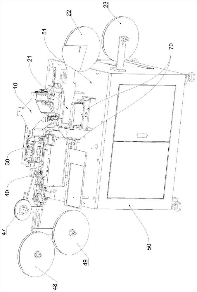
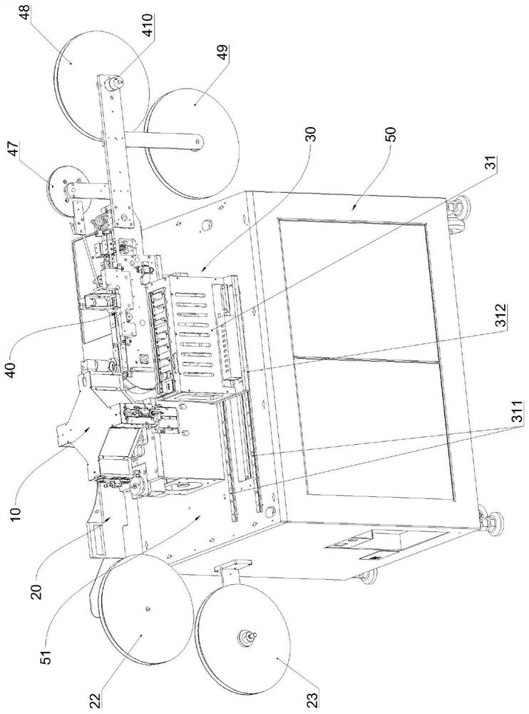
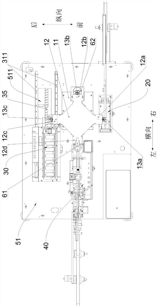
[0033] See figure 1 , figure 2 and image 3 , the automatic braiding type chip burning equipment of the present invention, it comprises working platform 51 and the braiding type chip feeding device 20 that is installed on the working platform, burning device 30, chip receiving and braiding device 40 and chip rotary conveyance Device 10, wherein burning device 30 comprises burner 32, and working platform 51 is fixedly installed on the top of equipment cabinet 50, and chip rotary conveyance device 10 comprises base 11, rotating rack 12 and chip suction mechanism, and base 11 is fixed on On the working platform 51, the longitudinal front side of the base 11 is the chip loading side, the longitudinal rear side is the chip programming side, and the horizontal left side is the chip unloading side. The outer peripheral surface of the rotating frame 12 has four protruding installation and the four installation ends are symmetrically distributed in a cross shape. The four installati...


PUM


Abstract

The invention provides full-automatic taped chip programming equipment. The full-automatic taped chip programming equipment can solve the problems that existing equipment is large in occupied space and an existing cantilever automatic chip programming machine is large in machining and assembling difficulty. According to the full-automatic taped chip programming equipment, a chip rotating conveyingdevice comprises a rotating frame, chip suction mechanisms and a base fixedly arranged on a working platform, wherein the longitudinal front side of the base is provided with a chip feeding side, thelongitudinal rear side of the base is provided with a chip programming side, and the transverse left side of the base is provided with a chip discharging side; four protruding mounting ends which aresymmetrically distributed in a cross shape are arranged on the peripheral face of the rotating frame, the four mounting ends are sequentially the first mounting end, the second mounting end, the third mounting end and the fourth mounting end in the anticlockwise direction, each of the first mounting end, the second mounting end and the third mounting end is provided with one chip suction mechanism correspondingly, and the rotating frame is rotatably arranged at the top of the base; and a taped chip feeding device and a chip receiving taping device are arranged on the chip feeding side and thechip discharging side respectively, and a programming device is movably arranged on the chip programming side.

Description

technical field [0001] The invention relates to the field of chip programming equipment, in particular to a fully automatic taping type chip programming equipment. Background technique [0002] The existing tape-type chip programming equipment generally uses a three-axis linkage system to drive the suction nozzle assembly between the chip programmer and the chip loading position of the tape machine, and between the chip programmer and the chip unloading position. The transfer of chips between positions can meet the requirements of automatic production, but due to the operating space requirements of the three-axis linkage mechanism, the existing tape-type chip programming equipment generally has the problem of bulky system and large space occupation. The Chinese invention patent with the notification number CN207903487U discloses a cantilever type automatic chip programming machine, which uses the dual arm function of the robot to control the rotary pendulum with a set of suc...

Claims


Application Information

Patent Timeline
Patent Type & Authority Applications(China)
IPC IPC(8): B65G49/07G11C11/00B65B15/04
CPCB65B15/04B65G49/07G11C11/00
Inventor 刘子康刘全保
Owner SUZHOU XINHUARUI ELECTRONICS
Why Eureka
Try Eureka