
Gear transmission stepless speed changer

A technology of continuously variable transmission and gear transmission, which is applied in the direction of gear transmission, transmission, transmission control, etc., can solve the problems of continuous variable speed output torque, continuous and uninterrupted power transmission, etc., and achieve simple structure, low cost, high torque smooth output

Pending Publication Date: 2020-09-18
徐宇
View PDF11 Cites 5 Cited by
  • Summary
  • Abstract
  • Description
  • Claims
  • Application Information

AI Technical Summary

Problems solved by technology

[0003] In order to overcome the shortcomings of the existing traditional hydraulic coupling automatic transmission AT and dual-clutch automatic transmission DCT that cannot achieve continuous power transmission and continuous variable speed output torque, this technical solution proposes a gear transmission continuously variable transmission with a new structure

Method used


Image

  • Gear transmission stepless speed changer
  • Gear transmission stepless speed changer
  • Gear transmission stepless speed changer

Examples


Embodiment Construction

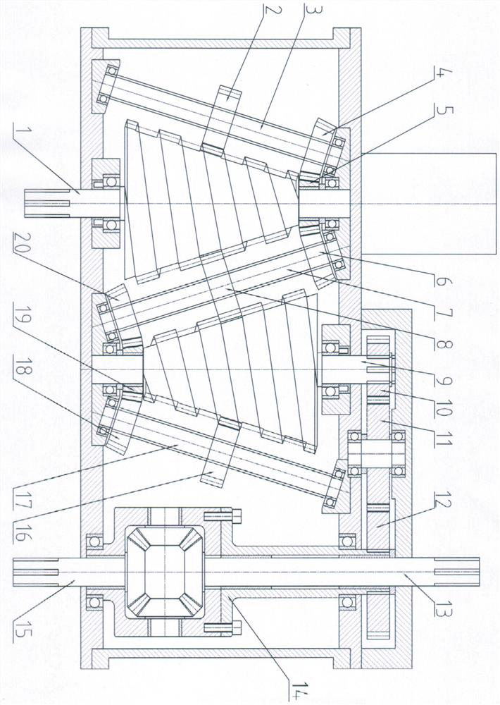
[0028] 1. The transmission process of transmission power input to output in turn:

[0029] in figure 1 Middle: (1) power input conical drum spiral belt gear→(2) power transmission synchronous gear 1, (8) power transmission synchronous gear 2, (16) power transmission synchronous gear 3→(9) power output conical drum spiral belt Gears.

[0030] In the process of power transmission, the power is input through (1) the conical drum spiral belt gear to rotate, and the meshing (2) power transmission synchronization gear 1, (8) power transmission synchronization gear 2, (16) power transmission synchronization Gear 3 rotates, and at the same time (2) power transmission synchronous gear 1, (8) power transmission synchronous gear 2, (16) power transmission synchronous gear 3 meshes with (9) power output cone drum spiral belt gear, thus driving (9) The power output cone drum spiral belt gear rotates, and then (10) reduction gear 1, (11) reduction gear 2, (12) reduction gear 3 drives (13) diffe...


PUM


Abstract

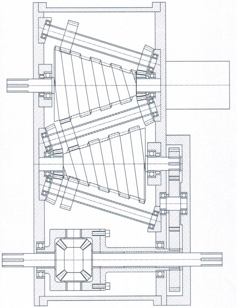
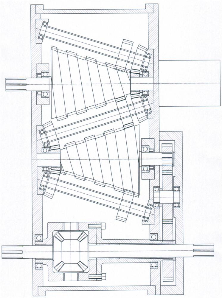
The invention discloses a gear transmission stepless speed changer. In a power transmission mechanism, please refer to the drawing 4 of the specification, power drives totally three power transmissionsynchronous gears which are arranged on the two sides of and between an input cone roller spiral strip-shaped gear and an output cone roller spiral strip-shaped gear and can move back and forth on three synchronous spline shafts for transmission through rotation of the input cone roller spiral strip-shaped gear, accordingly, the output cone roller spiral strip-shaped gear is driven to rotate, andthen a deceleration gear is used for driving a differential mechanism left half shaft and a right half shaft to output power torque. In a speed changing mechanism, please refer to the drawing 4 of the specification, rotation speed adjustment is achieved in the manner that a speed adjusting servo motor is utilized for driving a synchronous speed adjusting bevel gear to rotate, then, a synchronousspeed adjusting lead screw is driven to rotate, a synchronous speed adjusting shifting fork matched with the synchronous speed adjusting lead screw is driven to move back and forth in the axial direction of the synchronous speed adjusting lead screw, finally, the power transmission synchronous gears are driven to move back and forth on the three synchronous spline shafts at different meshing diameter positions between the input cone roller spiral strip-shaped gear and the output cone roller spiral strip-shaped gear, and accordingly different output rotation speeds are obtained.

Description

Technical field [0001] The technical solution relates to a speed change device in the process of power transmission, and is especially suitable for the speed change part after the power motor of the fuel vehicle engine and the new energy electric vehicle power motor outputs power. Background technique [0002] At present, all automatic transmissions matched on the power motors of fuel-fuel vehicle engines or new energy electric vehicles can be divided into two categories: automatic gear shifting and automatic stepless shifting. Automatic gear transmission has the characteristics of large output torque, but it has the disadvantages of complex structure, high maintenance cost, high fuel consumption, gear impact during driving, and poor comfort. The current automatic continuously variable transmission (CVT) is mainly based on the steel belt (or steel chain) friction cone wheel type continuously variable transmission, which can be changed by one steel belt (or steel chain) and two T...

Claims


Application Information

Patent Timeline
Patent Type & Authority Applications(China)
IPC IPC(8): F16H3/42F16H57/023F16H61/04F16H63/32
CPCF16H3/423F16H57/023F16H61/04F16H63/32
Inventor 徐宇
Owner 徐宇
Learn More