A diversion device that can be inserted into an internal combustion engine in both directions

A diversion device and internal combustion engine technology, applied in the direction of charging systems, mechanical equipment, engine components, etc., can solve the problems of increased manufacturing costs, difficult assembly, and decline

Inactive Publication Date: 2021-06-08
广东洋和环保科技有限公司
View PDF1 Cites 0 Cited by
  • Summary
  • Abstract
  • Description
  • Claims
  • Application Information

AI Technical Summary

Problems solved by technology

This action has certainly caused the air to be more active, but because of the drop in temperature caused by the rapid passing of the air, the effect of the far-infrared heating by the mesh 11 will be greatly reduced, and even more than figure 1 shown
[0005] As shown in the above two embodiments, it can be realized that its structure is complicated, the manufacturing cost will definitely increase relatively, and the assembly is not easy; what's more, if the component loses the ability to be fixed on the inner wall of the intake pipe due to aging of the component, so that some components If it is sucked into the internal combustion engine, the loss to consumers may not be a small sum

Method used


Image

  • A diversion device that can be inserted into an internal combustion engine in both directions
  • A diversion device that can be inserted into an internal combustion engine in both directions
  • A diversion device that can be inserted into an internal combustion engine in both directions

Examples


Embodiment Construction

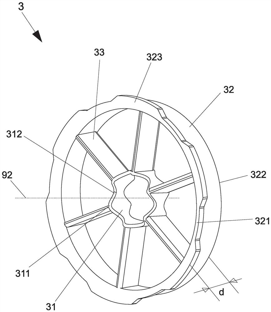
[0024] see Figure 3 to Figure 6 As shown, it is the three-dimensional structure of the preferred embodiment of the flow guide device that can be inserted into the internal combustion engine in two directions, the three-dimensional structure from another perspective, the front view, and the schematic diagram of the AA cross-sectional structure of the flow guide part. The flow guiding device 3 of the present invention, which can be bidirectionally inserted into an internal combustion engine, includes: a central ring structure 31 , an outer ring structure 32 and a plurality of flow guiding parts 33 . The core ring structure 31 is a hollow cylinder. In a preferred implementation of the present invention, the two ends of the core ring structure 31 have a plurality of flanges 311 and a plurality of grooves 312 , and the grooves 312 are arranged at intervals between the two flanges 311 , presenting a wave shape. The flow guiding portion 33 is connected to the flanges 311 on two end...


PUM


Abstract

The invention provides a diversion device that can be inserted into an internal combustion engine bidirectionally. It is inserted into the inner wall of an intake pipe of an internal combustion engine along a gas inlet direction. The diversion device includes a core ring structure, an outer ring structure and a plurality of diversion parts. The core ring structure is a hollow cylinder. The outer ring structure and the core ring structure are a hollow cylinder with the same axis, and the outer ring structure accommodates the core ring structure, the outer ring structure has a first end surface and a second end surface, the first end surface There is a distance from the second end surface. Each of the flow guiding parts defines an axial surface, each of the axial surfaces extends to the axis, and a plurality of the axial surfaces are arranged radially around the axis, and the flow guiding part connects the core ring structure and the outer ring structure. The above-mentioned air guiding part is designed such that only one side of the axial surface is designed with a quarter cylinder, and the first end surface and the second end surface are both provided with a quarter cylinder in a symmetrical manner.

Description

Technical field: [0001] The present invention relates to a flow guiding device, and in particular to a flow guiding device which can be placed into an internal combustion engine in different directions. Background technique: [0002] In modern life, automobiles and locomotives are indispensable means of transportation. However, the fuel required for the power of automobiles and locomotives when they start and operate, and the air pollution caused by the exhaust gas emitted, even cause environmental warming one of the causes of the phenomenon. In general, the power output of a vehicle internal combustion engine is almost determined by the amount of a certain proportion of air injected into the combustion chamber, and under different conditions and requirements, each gas has its optimal ratio of gas to fuel. If too much fuel lacks an appropriate proportion The gas cannot be burned, and the incomplete combustion produces a large amount of toxic waste gas, causing serious air p...

Claims


Application Information

Patent Timeline
Patent Type & Authority Patents(China)
IPC IPC(8): F02M35/10F02M27/04F02M27/06
CPCF02M27/04F02M27/06F02M35/10242F02M35/10262
Inventor 王睿杰
Owner 广东洋和环保科技有限公司
Why Eureka
Try Eureka