SLAM system and method for pipeline detection

A pipeline inspection and pipeline technology, which is applied in the direction of special pipes, pipe components, pipes/pipe joints/fittings, etc., can solve the problems of difficult to accurately determine the direction of pipelines, GNSS can not work, inertial navigation system superimposition, etc., to achieve enlarged measurement objects, Reduced axial error and high precision

Inactive Publication Date: 2020-09-22
李柏松 +1
View PDF9 Cites 5 Cited by
  • Summary
  • Abstract
  • Description
  • Claims
  • Application Information

AI Technical Summary

Problems solved by technology

[0005] However, it has the following defects. Long-distance oil and gas pipelines are often made of metal materials, which will greatly isolate electromagnetic signals and cause GNSS to fail to work. In addition, the main difficulty of modeling in long-distance pipelines is that their turns are extremely small (take a pipeline with a diameter of 1219mm as the For example, its maximum curvature radius is 1 / 50m^ -1 ), so the information collected by the existing airborne lidar used to scan the surrounding environment is difficult to accurately judge the direction of the pipeline, so the prediction of the direction of the pipeline and the calculation of its own pose can only be performed by the inertial navigation system (gyro Instrument) to complete, the error caused by the offset of the navigation system due to its own characteristics will seriously affect the small measurement value, and work for a long time in the long-distance oil and gas pipeline, the error of the inertial navigation system will continue to superimpose

Method used


Image

  • SLAM system and method for pipeline detection
  • SLAM system and method for pipeline detection

Examples


Embodiment Construction

[0026] In order to make the objectives, technical solutions, and advantages of the present invention clearer, the present invention will be described in further detail below. However, it should be understood that the specific embodiments described here are only used to explain the present invention, and are not used to limit the scope of the present invention.

[0027] Unless otherwise defined, all technical and scientific terms used herein have the same meaning as those commonly understood by those skilled in the technical field of the present invention. The terms used in the specification of the present invention herein are only for describing specific implementations. The purpose of the examples is not to limit the invention.

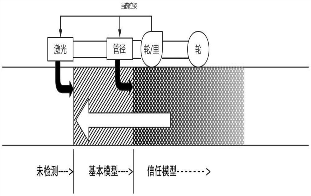
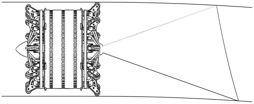
[0028] Such as figure 1 As shown, a SLAM (Instant Localization and Map Construction) system for pipeline inspection includes a pipeline robot and a controller. The pipeline robot moves in the pipeline, and also includes forward-looking lidar, A pipe diam...


PUM


Abstract

The invention discloses an SLAM system for pipeline detection. The SLAM system comprises a pipeline robot, a controller, a forward-looking laser radar, a pipe diameter measuring device and a mileage wheel, wherein the pipeline robot moves in a pipeline; and the forward-looking laser radar, the pipe diameter measuring device and the mileage wheel are respectively connected with the controller; theforward-looking laser radar is used for detecting information of a front unknown pipe section in the pipeline and transmitting the detected information to the controller to establish a basic model; the pipe diameter measuring device is used for measuring the pipe diameter information of the current position of the pipeline robot and transmitting the measured pipe diameter information to the controller, and the controller optimizes and adjusts the basic model to form a trust model; and the mileage wheel is used for measuring the distance information of the pipeline robot travelling along the central axis of the pipeline and transmitting the measured distance information to the controller, and the controller calculates the pose of the pipeline robot at the moment by combining the distance information and the trust model. The SLAM system for pipeline detection can help to locate the defects of the long-distance oil gas pipeline and model the surveying and mapping of the detected pipeline.

Description

Technical field [0001] The invention relates to a SLAM system and method for pipeline inspection, belonging to the field of pipeline inspection. Background technique [0002] As a device used to transport gases, liquids or fluids with solid particles, pipelines are widely used in petroleum, chemical and other industries. However, after long-term use, the pipeline is prone to problems such as chemical corrosion, mechanical damage and pipeline aging. Because pipelines are usually buried underground and have complicated layouts, they are often difficult or inaccessible to people. Therefore, it is very difficult to inspect and repair the pipelines. In response to the above situation, a pipeline robot was developed to replace workers to enter the pipeline for inspection and maintenance. [0003] During the use of pipeline robots, there are difficulties in positioning and modeling of the robot due to the electromagnetic shielding characteristics and non-identifying features of the pipe...

Claims


Application Information

Patent Timeline
Patent Type & Authority Applications(China)
IPC IPC(8): F16L55/28F16L55/48F16L101/30
CPCF16L55/28F16L55/48F16L2101/30
Inventor 李柏松于佳玮
Owner 李柏松
Why Eureka
Try Eureka