
Implantable molten ceramic material outflow device

A ceramic material, implanted technology, used in crucible furnaces, furnaces, lighting and heating equipment, etc., can solve problems affecting casting quality, human injury, particle size dispersion of ceramic sand, etc., to ensure stable and normal operation, and ensure smooth Production, the effect of improving the service life

Active Publication Date: 2020-09-22
JINGANG NEW MATERIALS
View PDF7 Cites 0 Cited by
  • Summary
  • Abstract
  • Description
  • Claims
  • Application Information

AI Technical Summary

Problems solved by technology

[0002] Sand casting is the main process of casting production. The castings produced by the sand casting process account for more than 70% of the total output of castings; sand is the aggregate that forms the mold and core in sand casting, and is an important molding material for sand casting. Its physical and chemical properties determine the performance of its casting process and affect the quality of castings; the raw sand used in sand casting in the foundry industry is mainly quartz sand, and its usage accounts for more than 90% of the amount of foundry sand; however, quartz sand Large thermal expansion, poor thermochemical stability under the action of metal oxides, castings are prone to casting defects such as sticky sand, veins, rough surface, etc., and a large amount of free SiO is produced during the production process 2 Therefore, quartz sand is not an ideal molding material for casting; in order to reduce the application of quartz sand in foundry production, artificial ceramic foundry sand came into being
[0003] Artificial ceramic casting sand has a round shape, high refractoriness, small thermal expansion, strong crush resistance, long service life, can save the amount of binder, improve the surface and dimensional accuracy of castings, and has been popularized and applied in casting production; The outlet of the fused ceramic sand preparation system is made of refractory materials directly on the furnace body. The shape is irregular and the outflow is very unstable. It is difficult to stably control the preparation process of the fused ceramic sand. The particle size of the sand is scattered, and the quality is very unstable

Method used


Image

  • Implantable molten ceramic material outflow device
  • Implantable molten ceramic material outflow device
  • Implantable molten ceramic material outflow device

Examples


Embodiment 1

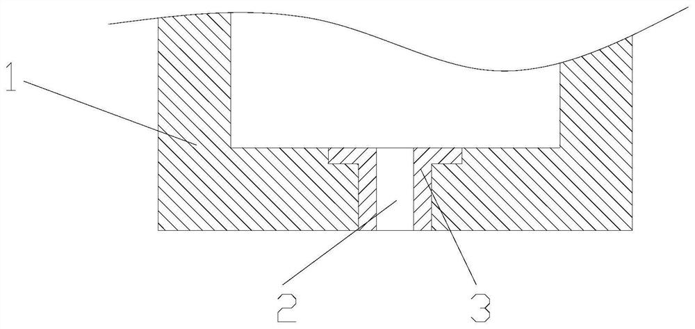
[0027] according to figure 1 As shown, an implantable molten ceramic material outflow device includes an outflow pipe 3, and the outflow pipe 3 is installed at the bottom of the furnace 1; the device can control the flow rate of the molten ceramic material through the outflow port 2, and realizes melting The stable flow control of ceramic materials not only ensures the particle size concentration of ceramic sand, but also ensures the quality of ceramic sand.

Embodiment 2

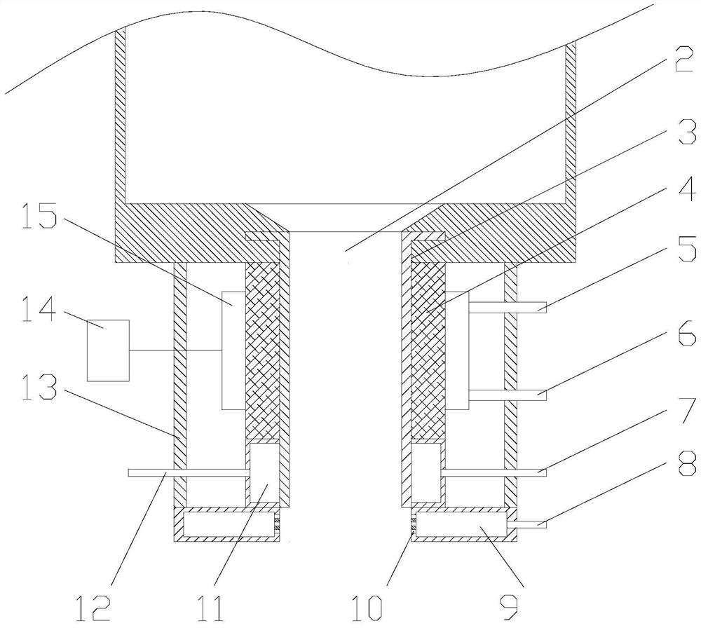
[0029] according to figure 2The difference from Example 1 is that the lower end of the outflow pipe 3 extends to the outside of the furnace 1, and an insulating refractory lining 4 and a protective shell 13 are installed on the outflow pipe 3 extending outside the furnace 1, so The heat-insulating and refractory lining 4 is set on the outside of the outlet pipe 3, and a first cooling jacket 11 is provided at the bottom of the heat-insulating and refractory lining 4. The protective shell 13 is installed on the outside of the heat-insulating and refractory lining 4, and the protective shell 13 The top of the furnace is installed on the bottom of the furnace 1, and the first cooling jacket 11 is set on the outlet pipe 3. One side of the first cooling jacket 11 is provided with a first cooling water inlet pipe 7, and the other side is provided with a first cooling water inlet pipe 7. The water outlet pipe 12 is equipped with an induction heater 15 on the outside of the heat-insul...

Embodiment 3

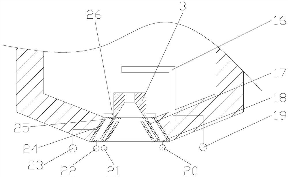
[0037] according to image 3 As shown, the difference with Embodiment 1 and Embodiment 2 is that the outlet pipe 3 is arranged in the inside of the furnace 1, and the bottom of the outlet pipe 3 is provided with a top plate 25, a bottom plate 18, an outlet pipe 3, and a negative electrode. The connection terminal 23 is provided with a heat-resistant electrode 16 inside the melting furnace 1, and the heat-resistant electrode 16 is arranged above the outlet pipe 3, and one end of the heat-resistant electrode 16 is installed on the bottom of the melting furnace 1, and the heat-resistant electrode 16 The positive terminal 19 is installed on the top plate 25, and a nut 26 is fixed on the top plate 25. Threads are provided on the outside of the outlet pipe 3, and are matched with the nut 26. The outlet pipe 3 is connected with the negative terminal 23. The top plate 25 is fixed on the inner side of the bottom of the melting furnace 1, the bottom plate 18 is fixed on the outside of t...


PUM

PropertyMeasurementUnit
poweraaaaaaaaaa

Abstract

The invention discloses an implantable molten ceramic material outflow device. The implantable molten ceramic material outflow device comprises an outflow pipe, wherein the outflow pipe is mounted atthe bottom of a smelting furnace. According to the implantable molten ceramic material outflow device, opening and closing of a flow outlet can be achieved through an electric heating mode, and meanwhile, the flow rate of a molten ceramic material of the flow outlet can be controlled by controlling the size of current, the stable flow control over the molten ceramic material is achieved, the particle size concentration of ceramic sand is guaranteed, and the quality of the ceramic sand can further be guaranteed.

Description

technical field [0001] The invention belongs to the technical field of preparation of molten ceramic particles, in particular to an implantable molten ceramic material outflow device. Background technique [0002] Sand casting is the main process of casting production. The castings produced by the sand casting process account for more than 70% of the total output of castings; sand is the aggregate that forms the mold and core in sand casting, and is an important molding material for sand casting. Its physical and chemical properties determine the performance of its casting process and affect the quality of castings; the raw sand used in sand casting in the foundry industry is mainly quartz sand, and its usage accounts for more than 90% of the amount of foundry sand; however, quartz sand Large thermal expansion, poor thermochemical stability under the action of metal oxides, castings are prone to casting defects such as sticky sand, veins, rough surface, etc., and a large amo...

Claims


Application Information

Patent Timeline
Patent Type & Authority Applications(China)
IPC IPC(8): F27B14/04F27B14/14F27B14/18F27B14/20F27D7/06
CPCF27B14/04F27B14/0806F27B14/14F27B14/20F27D7/06F27B2014/0887F27D2007/063
Inventor 赵华星
Owner JINGANG NEW MATERIALS
Learn More