
Optical storage method and system based on fused quartz fluorescence signals

A technology of fused silica and fluorescent signals, applied in the field of optical storage, can solve the problems of low storage density, achieve high storage density, expand storage dimensions, and increase storage capacity

Active Publication Date: 2020-09-22
HUAZHONG UNIV OF SCI & TECH
View PDF7 Cites 2 Cited by
  • Summary
  • Abstract
  • Description
  • Claims
  • Application Information

AI Technical Summary

Problems solved by technology

[0004] Aiming at the above defects or improvement needs of the prior art, the present invention provides an optical storage method and system based on fused silica fluorescent signals to solve the technical problem of low storage density in the prior art

Method used


Image

  • Optical storage method and system based on fused quartz fluorescence signals
  • Optical storage method and system based on fused quartz fluorescence signals

Examples


Embodiment 1

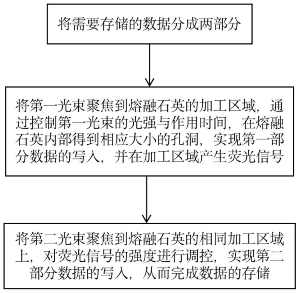
[0034] A method of optical storage based on fused silica fluorescent signals, such as figure 1 shown, including the following steps:

[0035] S1. Divide the data to be stored into two parts;

[0036] S2. Focus the first light beam on the processing area of ​​fused silica. By controlling the light intensity and action time of the first light beam, holes of corresponding size are obtained inside the fused silica to realize the writing of the first part of data and generate fluorescence in the processing area. Signal;

[0037] Specifically, in this embodiment, the first light beam is a femtosecond laser with a wavelength of λ 1 . Based on the scattering of visible light by the holes, ordinary optical microscopes can be used to image these holes to realize the reading of this part of the data. The size of the hole is positively correlated with the intensity and action time of the laser pulse. The greater the intensity, the longer the action time, and the larger the hole. Furt...

Embodiment 2

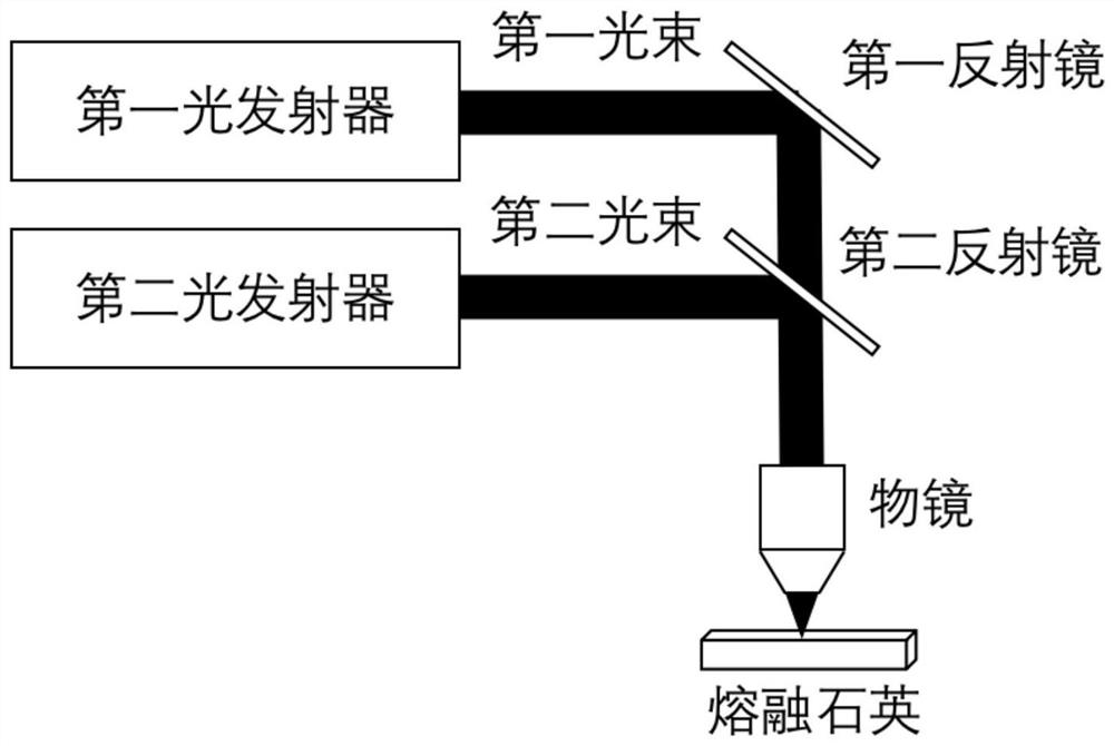
[0041] An optical storage system based on fused silica fluorescent signals, such as figure 2 As shown, including: a first light emitter, a first reflector, a second light emitter, a second reflector, an objective lens and fused silica;

[0042] The first light emitter is used to generate the first light beam and control the light intensity of the first light beam; specifically, in this embodiment. The first beam is a femtosecond laser with a wavelength of λ 1 .

[0043]The first reflector is used to reflect the first light beam onto the second reflector;

[0044] The second mirror is used to transmit the first light beam to the objective lens;

[0045] The objective lens is used to focus the first light beam onto the processing area of ​​the fused silica;

[0046] Fused silica is used to obtain holes of corresponding size inside based on the different light intensity and action time of the first beam, realize the writing of the first part of data, and generate fluorescent...


PUM


Abstract

The invention discloses an optical storage method and system based on fused quartz fluorescence signals. The optical storage method comprises the following steps: S1, dividing data needing to be stored into two parts; S2, focusing the first light beam to a processing area of the fused quartz, obtaining a hole with a corresponding size in the fused quartz by controlling the light intensity and theaction time of the first light beam, realizing writing of first part data, and generating a fluorescence signal in the processing area; and S3, focusing the second light beam to the same processing area of the fused quartz, regulating and controlling the intensity of the fluorescence signal, and realizing the writing of the second part of data, thereby finishing the storage of the data. The optical scattering signals and the fluorescence signals of the processing structure are adopted to store data respectively, the storage dimension of optical storage is expanded, more data can be stored on fused quartz with the same size, the storage capacity is greatly improved, and the storage density is high.

Description

technical field [0001] The invention belongs to the field of optical storage, and more specifically relates to an optical storage method and system based on fused silica fluorescent signals. Background technique [0002] In recent years, with the rapid development of information technologies such as the Internet and the Internet of Things, the amount of data generated by humans in production and life has also exploded. For enterprises, data centers and other institutions, how to effectively save these massive data is an important challenge. The current mainstream storage technologies often have certain disadvantages when faced with new demands. For example, common hard disks (HDD, SSD, etc.) consume a lot of power during use, and the service life of these devices is not long. Data needs to be transcribed every 3 to 5 years, which is not suitable for long-term data storage. Storage media such as optical disks and magnetic tapes are limited by materials, and have a service l...

Claims


Application Information

Patent Timeline
Patent Type & Authority Applications(China)
IPC IPC(8): G11B7/1362G11B7/1374G11B7/139
CPCG11B7/1362G11B7/1374G11B7/139
Inventor 张静宇高骥超刘思垣
Owner HUAZHONG UNIV OF SCI & TECH
Learn More