
Inductively coupled isolator, high-voltage signal acquisition system and industrial control system

An inductive coupling and isolator technology, which is applied in the field of isolators, can solve the problems of large coupled inductance, poor withstand voltage characteristics, and high power consumption of optocoupler isolators.

Pending Publication Date: 2020-09-22
HANGZHOU RUIMENG TECH
View PDF0 Cites 2 Cited by
  • Summary
  • Abstract
  • Description
  • Claims
  • Application Information

AI Technical Summary

Problems solved by technology

Among them, the power consumption of the optical coupling isolator is large, the signal frequency is low, the life is short, and the two-way transmission of data cannot be carried out; the circuit structure of the capacitive coupling isolator is complex, the chip area is large, and it will couple a certain instantaneous voltage on the isolated side to the non-isolated On the side, it is inferior to the optical coupling isolator in terms of withstand voltage characteristics; the inductive coupler is the preferred choice of the current data isolator because of its good withstand voltage characteristics, long service life and simple codec circuit. mainstream structure
[0004] In the process of using an inductive coupling isolator to isolate the non-isolated side and the isolated side, since the isolated side and the non-isolated side cannot directly perform bidirectional data transmission, the data transmission between the isolated side and the non-isolated side needs to use two pairs of coupling inductors Yes, that is, a pair of coupled inductors is required to transmit data from the non-isolated side to the isolated side, and another pair of coupled inductors is required to transmit data from the isolated side to the non-isolated side. Large, which will cause the inductive coupling isolator to occupy a large space volume, and thus limit the application range of the inductive coupling isolator in actual production
At present, there is no effective solution to this technical problem

Method used


Image

  • Inductively coupled isolator, high-voltage signal acquisition system and industrial control system
  • Inductively coupled isolator, high-voltage signal acquisition system and industrial control system
  • Inductively coupled isolator, high-voltage signal acquisition system and industrial control system

Examples


Embodiment Construction

[0030] The following will clearly and completely describe the technical solutions in the embodiments of the present invention with reference to the accompanying drawings in the embodiments of the present invention. Obviously, the described embodiments are only some, not all, embodiments of the present invention. Based on the embodiments of the present invention, all other embodiments obtained by persons of ordinary skill in the art without making creative efforts belong to the protection scope of the present invention.

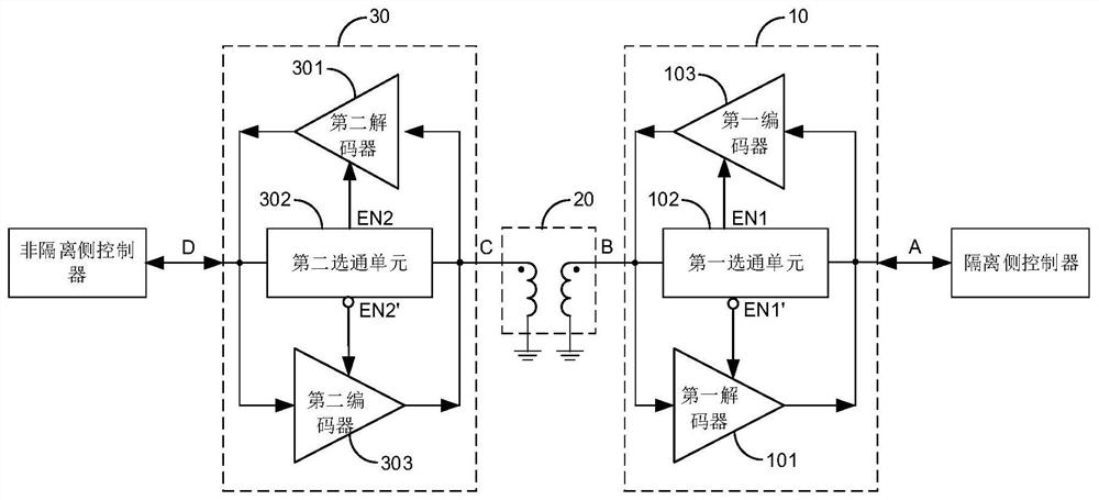
[0031] See figure 1 , figure 1 A structural diagram of an inductively coupled isolator provided in an embodiment of the present invention, the inductively coupled isolator includes:

[0032] The first codec circuit 10 is configured to transmit the first data sent by the isolated side controller to the second codec circuit 30 through the coupled inductor pair 20 when receiving the first start signal sent by the isolated side controller ; When receiving the fi...


PUM


Abstract

The invention discloses an inductive coupling isolator, which comprises: a coupling inductor pair; a first encoding and decoding circuit which is used for transmitting first data to a second encodingand decoding circuit through the coupling inductor pair when a first starting signal is received, wherein when a first termination signal is received, sending the first data to the second encoding anddecoding circuit is stopped, and a non-isolated side controller is notified to prepare to send the second data; and a second encoding and decoding circuit which is used for receiving the first data,notifying the non-isolated side controller to prepare to send second data when receiving the first termination signal, and transmitting the second data to the first encoding and decoding circuit through the coupling inductor pair, wherein when a second termination signal is received, sending the second data to the first encoding and decoding circuit is stopped, and an isolation side controller isnotified to send the data of the next period by using the second termination signal. Only one coupling inductor pair is used in the isolator, so that the space volume occupied by the inductive couplercan be reduced.

Description

technical field [0001] The invention relates to the technical field of isolators, in particular to an inductive coupling isolator, a high-voltage signal acquisition system and an industrial control system. Background technique [0002] In the field of industrial control, the operating current of many industrial electrical systems can be as high as hundreds of amperes, which will form a huge instantaneous surge current between the power supply and the ground wire, and cause huge damage to the electrical control equipment. In the prior art, in order to collect and control the data signals in the industrial electrical system, an isolator is usually used to isolate the high-voltage system with a large surge current from the low-voltage system with a small current, and at the same time in the high-voltage system The two sides of the low-voltage system and the low-voltage system adopt independent power supply systems and ground wires, so that only digital signals can be transmitte...

Claims


Application Information

Patent Timeline
IPC IPC(8): H03K19/0175G05B19/04G05B19/048
CPCG05B19/04G05B19/048H03K19/017545H03K19/01759
Inventor 翟理王建国
Owner HANGZHOU RUIMENG TECH
Learn More