Fan control method in ultraviolet curing equipment and ultraviolet curing equipment

A curing equipment, UV technology, applied in pump control, mechanical equipment, machine/engine, etc., can solve the problems of unstable cooling effect and unstable wind pressure

Pending Publication Date: 2020-09-25
BEIJING NAURA MICROELECTRONICS EQUIP CO LTD
View PDF8 Cites 1 Cited by
  • Summary
  • Abstract
  • Description
  • Claims
  • Application Information

AI Technical Summary

Problems solved by technology

[0005] The purpose of the embodiment of the present invention is to provide a fan control method in ultraviolet curing equipment and ultraviolet curing equipment to solve the problem in the prior art that the cooling effect is unstable due to the unstable wind pressure when performing the ultraviolet curing process

Method used


Image

  • Fan control method in ultraviolet curing equipment and ultraviolet curing equipment
  • Fan control method in ultraviolet curing equipment and ultraviolet curing equipment
  • Fan control method in ultraviolet curing equipment and ultraviolet curing equipment

Examples


Embodiment 1

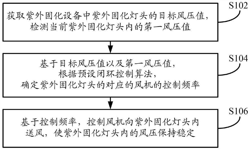
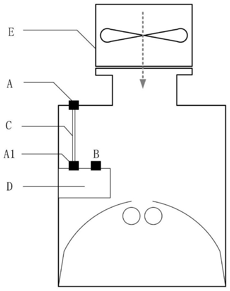
[0077] Such as figure 1 As shown, the embodiment of the present invention provides a fan control method in ultraviolet curing equipment. The execution subject of the method may be the controller of the ultraviolet curing equipment, or it may be an ultraviolet curing equipment with a current adjustment mechanism, or it may be an ultraviolet curing equipment. The server of the device can be an independent server or a server cluster composed of multiple servers. The method specifically may include the following steps:

[0078] In S102, the target wind pressure value of the ultraviolet curing lamp head in the ultraviolet curing device is obtained, and the first wind pressure value in the current ultraviolet curing lamp head is detected.

[0079] The principle of ultraviolet curing (that is, UV Cure) is to use the energy of high-energy photons to "break" and reconstruct the chemical bonds in the film to form new chemical bonds and network structures, thereby reducing the dielectri...

Embodiment 2

[0092] Such as Figure 4 As shown, the embodiment of the present invention provides a fan control method in ultraviolet curing equipment, the method may specifically include the following steps:

[0093] In S402, the first wind pressure value in the current ultraviolet curing lamp head is detected.

[0094] For the specific processing procedure of the above S402, reference may be made to the related content of S102 in the above Embodiment 1, which will not be repeated here.

[0095] In S404, the lamp head power of the ultraviolet curing lamp head is obtained, and based on the preset corresponding relationship between the lamp head power and the target wind pressure value, the target wind pressure value corresponding to the lamp head power is obtained.

[0096] Preferably, according to the heating level and cooling requirements of the UV curing lamp head under different powers, a power and wind pressure correspondence table (that is, the preset correspondence between the lamp ...

Embodiment 3

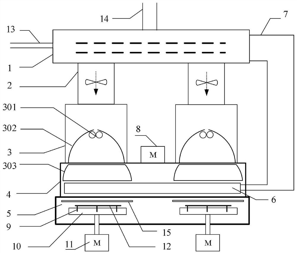
[0123] The above is the fan control method in the ultraviolet curing equipment provided by the embodiment of the present invention. Based on the same idea, the embodiment of the present invention also provides a fan control device in the ultraviolet curing equipment, such as Image 6 shown.

[0124] The fan control device in the ultraviolet curing equipment includes: a first acquisition module 601, a first determination module 602 and a control module 603, wherein:

[0125] The first acquisition module 601 is used to acquire the target wind pressure value of the ultraviolet curing lamp head in the ultraviolet curing equipment, and detect the first wind pressure value in the current ultraviolet curing lamp head;

[0126] The first determination module 602 is configured to determine the control frequency of the corresponding fan of the UV curing lamp head according to the preset closed-loop control algorithm based on the target wind pressure value and the first wind pressure val...


PUM


Abstract

The embodiment of the invention discloses a fan control method in ultraviolet curing equipment and the ultraviolet curing equipment. The fan control method comprises the steps that a target wind pressure value of an ultraviolet curing lamp holder in the ultraviolet curing equipment is obtained, a first wind pressure value in the ultraviolet curing lamp holder at present is detected; based on the target wind pressure value and the first wind pressure value, the control frequency of a fan corresponding to the ultraviolet curing lamp holder is determined according to a preset closed-loop controlalgorithm; and based on the control frequency, the fan is controlled to supply air into the ultraviolet curing lamp holder. By means of the fan control method in the ultraviolet curing equipment, theair pressure in the ultraviolet curing lamp holder can be kept stable.

Description

technical field [0001] The invention relates to the technical field of semiconductor equipment, in particular to a fan control method in ultraviolet curing equipment and the ultraviolet curing equipment. Background technique [0002] In the field of semiconductors, UV-assisted heat treatment is to use the characteristics of high energy (short wavelength and high light energy) of ultraviolet light to modify the deposited film. This process is called UV curing (UV Cure). The UV light source generally adopts a stepless mercury lamp. The device will also generate a large amount of heat energy during the process of emitting ultraviolet light, which will cause the temperature of the light source to rise. It must be fully cooled by a circulating air cooling system to prevent the device from being overheated and damaged. [0003] In the actual application process, the cooling effect is generally measured by the wind pressure of the cooling wind. The greater the wind pressure, the mo...

Claims


Application Information

Patent Timeline
Patent Type & Authority Applications(China)
IPC IPC(8): B05D3/06F04D27/00
CPCB05D3/067F04D27/00
Inventor 魏延宝
Owner BEIJING NAURA MICROELECTRONICS EQUIP CO LTD
Why Eureka
Try Eureka