Heavy-load truss transfer robot

A technology for handling robots and trusses, which is used in manipulators, program-controlled manipulators, non-electric welding equipment, etc., can solve the problems of high feeding cost and low feeding efficiency, save labor, accurate and efficient feeding process, and reduce processing costs. Effect

Inactive Publication Date: 2020-09-25
GUANGXI RUIKE IND ROBOT CO LTD +1
View PDF5 Cites 0 Cited by
  • Summary
  • Abstract
  • Description
  • Claims
  • Application Information

AI Technical Summary

Problems solved by technology

[0004] The technical problem to be solved by the present invention is to provide a heavy-duty truss handling robot to solve t

Method used


Image

  • Heavy-load truss transfer robot
  • Heavy-load truss transfer robot
  • Heavy-load truss transfer robot

Examples


Embodiment Construction

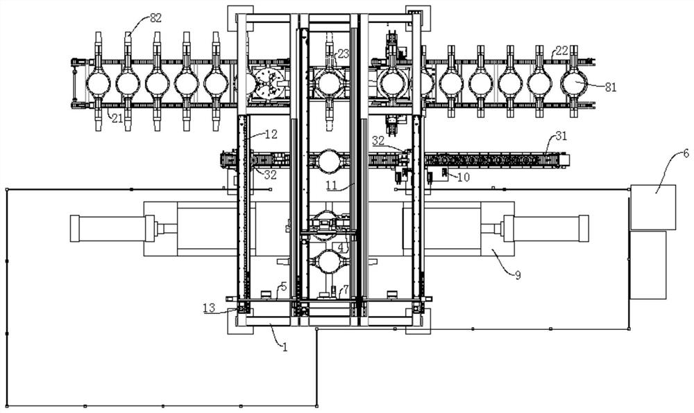
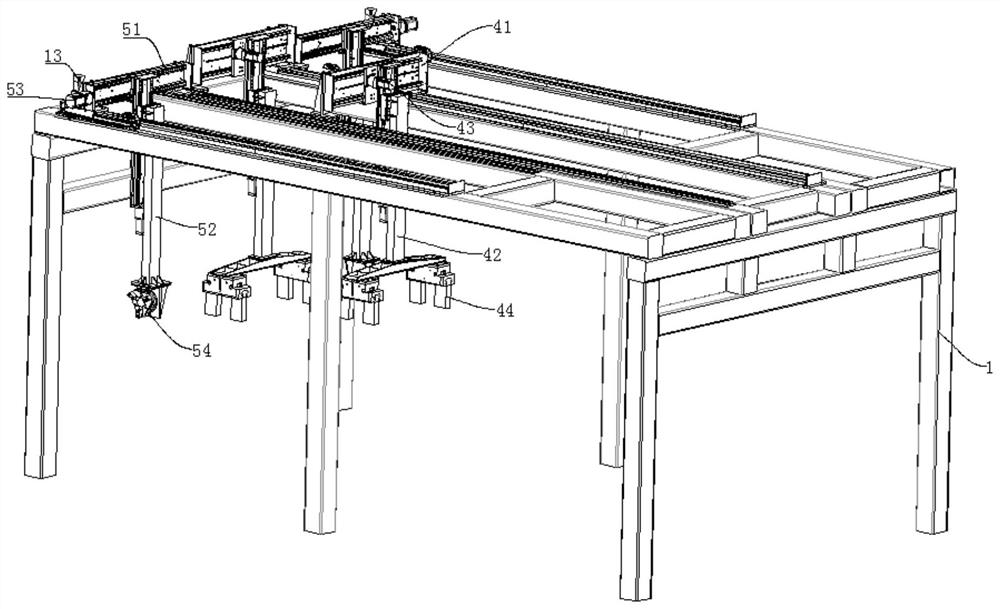
[0027] Such as Figure 1 to Figure 4 As shown, a heavy-duty truss handling robot includes a truss 1, an axle housing conveying device, a shaft head feeding device, an axle housing grabbing manipulator, and a shaft head feeding manipulator, and the axle housing conveying device and The shaft head feeding device and the axle housing conveying device are located in front of the shaft head feeding device, and the clamping welding area is formed under the rear part of the truss 1 .

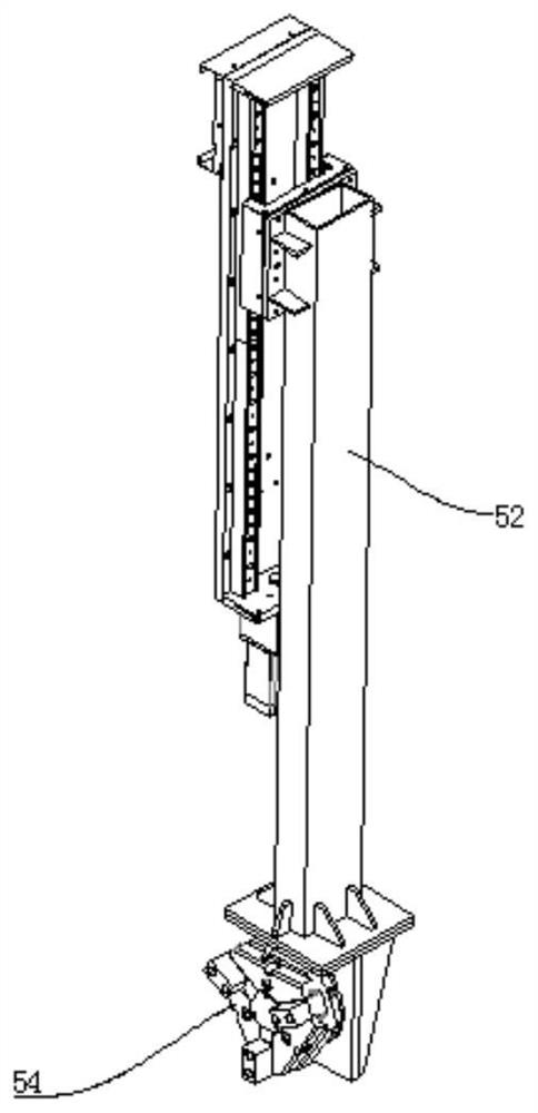
[0028] The top of the truss 1 is provided with a first slide rail 11 between the axle housing conveying device and the clamping welding area, and the axle housing grabbing manipulator is slid on the first slide rail 11, and the axle housing grabbing manipulator includes a first support beam 41, The first lifting arm 42, the second driving device 43 and the mechanical gripper 44, the first support beam 41 is arranged laterally and slides on the first slide rail 11, and the upper end of the first lifting...


PUM


Abstract

The invention provides a heavy-load truss transfer robot. The heavy-load truss transfer robot comprises a truss, an axle housing conveying device, an axle head feeding device, axle housing grabbing manipulators, axle head feeding manipulators and a control device, wherein a clamping and welding area is formed under the rear of the truss; first sliding rails are arranged on the top of the truss andare located between the axle housing conveying device and the clamping and welding area; the axle housing grabbing manipulators are arranged on the first sliding rails in a sliding manner; second sliding rails are arranged on the top of the truss and are located between the axle head feeding device and the clamping and welding area; the axle head feeding manipulators are arranged on the second sliding rails in a sliding manner; the axle housing conveying device comprises a first chain plate conveying mechanism, a second chain plate conveying mechanism, and a rotary table transfer trolley; theaxle head feeding device comprises a third chain plate conveying mechanism and turnover devices; the third chain plate conveying mechanism is transversely arranged and is located below the axle headfeeding manipulators; and the turnover devices are arranged on the third chain plate conveying mechanism and are located at the outer sides of the second sliding rails. The heavy-load truss transfer robot can solve the technical problems of high feeding cost and low feeding efficiency in the process of welding an axle head on an axle housing.

Description

technical field [0001] The invention relates to the technical field of axle housing processing, in particular to a heavy-duty truss handling robot. Background technique [0002] Friction welding refers to that under the action of pressure, under the action of constant or increasing pressure and torque, the relative motion between the welding contact end surfaces is used to generate frictional heat and plastic deformation heat on the friction surface and its surrounding areas, so that its The temperature in the nearby area rises to a temperature range close to but generally lower than the melting point, the deformation resistance of the material decreases, the plasticity increases, and the oxide film on the interface is broken. A solid-state welding method that achieves welding by diffusion and recrystallization. [0003] The rear axle housing assembly is an important load-bearing part of the vehicle, which bears about 2 / 3 of the total mass of the vehicle, which is related t...

Claims


Application Information

Patent Timeline
IPC IPC(8): B23K20/12B25J9/00
CPCB23K20/1245B25J9/0075
Inventor 黄庚保梁梅
Owner GUANGXI RUIKE IND ROBOT CO LTD
Why Eureka
Try Eureka