Continuous biomass carbonization device and method

A biomass carbonization device technology, applied in rotary carbonization furnaces, special forms of dry distillation, petroleum industry, etc., can solve the problems of screw shaft bending, easy blockage of exhaust pipes, affecting the normal operation of equipment, etc., to increase added value. Effect

Pending Publication Date: 2020-09-25
INT CENT FOR BAMBOO & RATTAN
View PDF0 Cites 0 Cited by
  • Summary
  • Abstract
  • Description
  • Claims
  • Application Information

AI Technical Summary

Problems solved by technology

Some moving bed equipment lengthens the conveying length of the screw in order to prolong the residence time of the material in the heating zone. During the operation of the equipment, the screw shaft is prone to bending, resulting in the material being stuck and unable to be conveyed normally.
Some moving bed equipment adopts multi-stage screw conveying, each stage is independently set power, so that the conveying speed of the material cannot be matched, and it is easy to cause material blockage
In addition, the tar generated during the pyrolysis and carbonization of biomass is easy to block the exhaust pipe, and many equipment designs do not consider the dredging of the pipeline, which affects the normal operation of the equipment

Method used


Image

  • Continuous biomass carbonization device and method

Examples


Embodiment 1

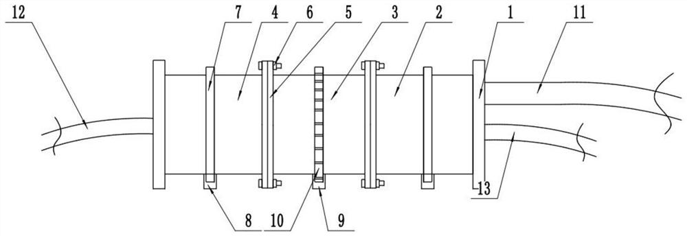
[0032] Such as figure 1 As shown, this embodiment provides a continuous biomass carbonization device, including a frame 1 and a roasting cylinder 2 and a pyrolysis carbonization cylinder 3 that are rotatably mounted on the frame 1, wherein the frame 1 includes two parallel Circular support seat, the lower part of the support seat is fixed by the bottom bracket, the front feed port of the roasting cylinder 2 is connected to the first circular support seat in rotation, and the support seat is provided with a feed port, an exhaust port and a roasting The cylinder 2 is connected, the feed port is used to connect the feed pipe 11, and the exhaust port is used to connect the exhaust pipe 13, and the feed pipe 11 and the exhaust pipe 13 are all provided with valves, preferably ball valves; the roasting cylinder 2 and The pyrolysis and carbonization cylinder 3 is connected in sequence, the roasting cylinder 2 is used for roasting biomass, the pyrolysis and carbonization cylinder 3 is ...

Embodiment 2

[0049] This embodiment is an improvement made on the basis of Embodiment 1. The improvement is that it also includes an activation cylinder 4, the front end feed port of the activation cylinder 4 and the discharge port of the pyrolysis and carbonization cylinder 3 connected, the rear end of the activation cylinder 4 is rotationally connected with the second support seat, and the rear end of the activation cylinder 4 is provided with a discharge port. When working, the discharge port is closed. After the work is completed, the discharge port is opened for In connection with the carbon box; the activation cylinder 4 is also provided with an activation device, which includes a self-activation device and / or a microwave activation device;

[0050] In this embodiment, the self-activation device includes a self-activation pipe, the exhaust pipe 13 is connected with a steam boiler, the inlet of the self-activation pipe is connected with the steam outlet of the steam boiler, and the sel...

Embodiment 3

[0058] This embodiment is an improvement on the basis of Embodiments 1 and 2. The improvement is that a discharge port is provided at the bottom of the second support seat, and the discharge port is connected with the activation cylinder 4 or the pyrolysis carbonization cylinder 3 Connection, the discharge port is connected with the carbon box through the discharge pipe, and a valve is set at the discharge port.


PUM

PropertyMeasurementUnit
specific surface areaaaaaaaaaaa

Abstract

The invention discloses a continuous biomass carbonization device and method, belonging to the technical field of biomass charcoal production. The continuous biomass carbonization device comprises a frame, a roasting cylinder and a pyrolysis and carbonization cylinder, wherein the roasting cylinder and the pyrolysis and carbonization cylinder are rotationally installed on the frame and sequentially communicate with each other in a front-to-back direction, the roasting cylinder is used for roasting biomass, the pyrolysis carbonization cylinder is used for pyrolyzing and carbonizing the biomass,the roasting cylinder and the pyrolysis and carbonization cylinder are connected with a driving device, a feeding hole is formed in the front end of the roasting cylinder, the pyrolysis and carbonization cylinder is connected with a carbon box, heating devices are arranged on the outer surfaces of the roasting cylinder and the pyrolysis and carbonization cylinder, the roasting cylinder is connected with an exhaust pipe, and the driving device and the heating devices are all connected with a control device. The device and the method can realize continuous carbonization production.

Description

technical field [0001] The invention relates to the technical field of biomass charcoal production, in particular to a continuous biomass carbonization device and method. Background technique [0002] The existing biomass carbonization equipment has two types: fixed bed and moving bed. Most of the fixed bed equipment is improved on the basis of the original carbonization earth kiln or gasifier. The temperature controllability is poor, and it cannot meet the requirements of various biomass raw materials and different carbonization process parameters. The product quality is uneven and the production cycle is long. And it is intermittent production. Compared with fixed bed equipment, the advantage of moving bed equipment is continuous production and controllable carbonization temperature. However, the heating speed is too fast and the carbonization time is short, resulting in more liquefied products and low carbon yield. [0003] According to the characteristics of biomass p...

Claims


Application Information

Patent Timeline
Patent Type & Authority Applications(China)
IPC IPC(8): C10B53/00C10B1/10
CPCC10B1/10C10B53/00
Inventor 刘志佳冯子兴杨建飞倪良萌高奇何玉玉侯艳梅
Owner INT CENT FOR BAMBOO & RATTAN
Why Eureka
Try Eureka