Thermoelectric energy storage power generation device and power generation method thereof

An energy storage power generation and temperature difference technology, which is applied to electrical components, machines/engines, and electrical energy storage systems, etc., can solve the problems of high pressure and high cost of reservoir equipment, and achieve the effect of small storage capacity and low internal pressure.

Pending Publication Date: 2020-09-25
陆盛宏
View PDF7 Cites 0 Cited by
  • Summary
  • Abstract
  • Description
  • Claims
  • Application Information

AI Technical Summary

Problems solved by technology

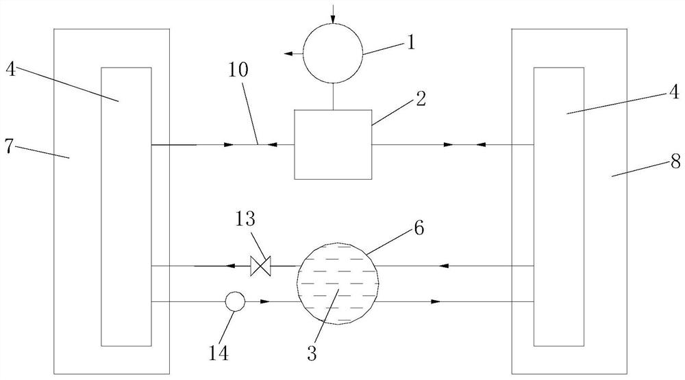
[0003] The technical problem to be solved by the embodiments of the present invention is to provide a temperature difference energy storage power generation device and its power generation method, which aims to solve the problem of high internal pressure of the reservoir equipment in the prior art where the power generation method is to convert electric energy into hydromechanical energy and store it. resulting in high cost

Method used


Image

  • Thermoelectric energy storage power generation device and power generation method thereof
  • Thermoelectric energy storage power generation device and power generation method thereof
  • Thermoelectric energy storage power generation device and power generation method thereof

Examples


Embodiment Construction

[0021] In order to make the object, technical solution and advantages of the present invention clearer, the present invention will be further described in detail below in conjunction with the accompanying drawings and embodiments. It should be understood that the specific embodiments described here are only used to explain the present invention, not to limit the present invention.

[0022] In the description of the present invention, it should be noted that the terms "center", "upper", "lower", "left", "right", "vertical", "horizontal", "inner", "outer" etc. The indicated orientation or positional relationship is based on the orientation or positional relationship shown in the drawings, and is only for the convenience of describing the present invention and simplifying the description, rather than indicating or implying that the referred device or element must have a specific orientation, or in a specific orientation. construction and operation, and therefore cannot be constru...


PUM


Abstract

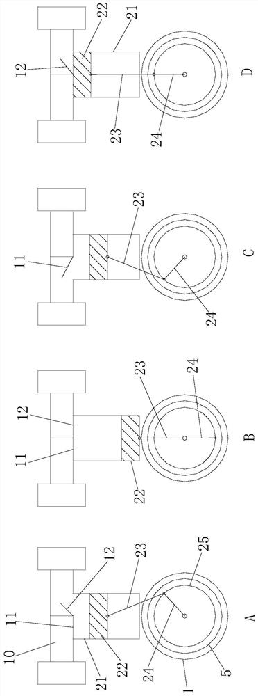
The invention belongs to the technical field of energy storage power generation, and provides a thermoelectric energy storage power generation device and a power generation method thereof. The thermoelectric energy storage power generation device comprises a motor, a transmission mechanism, a refrigerant, heat exchangers, a flywheel and a liquid storage device, wherein heat exchangers are arrangedin a tank A for storing water and a tank B for storing water, a low-temperature heat source tank A, the heat exchangera and a high-temperature heat source tank B form a closed circulating system; when the power grid consumes electricity at low ebb, electric energy is consumed to transfer heat from the low temperature heat source tank A to the high temperature heat source tank B, and the heat is stored in an internal energy form; and at the peak of power utilization of a power grid, a liquid refrigerant is evaporated from the high temperature heat source tank B to become a gaseous refrigerantto push the flywheel to drive an engine to generate power, internal energy is converted into electric energy, and then the gaseous refrigerant is fed into the low temperature heat source tank A to release liquefaction heat to become the liquid refrigerant to be stored for multiple times of recycling. According to the device, power generation is carried out after temperature difference energy storage is carried out in an internal energy form, and the device has the advantages of being small in water storage capacity and small in internal pressure.

Description

technical field [0001] The invention belongs to the technical field of energy storage power generation, and in particular relates to a temperature difference energy storage power generation device and a power generation method thereof. Background technique [0002] At present, the energy storage power generation method generally adopts the conversion of electrical energy into water mechanical energy and stores it. The mechanical energy of water is WK=mgh, where g=9.8N / kg. When the WK is relatively large, the quality of the water is very large, and the water level difference h is relatively large. As far as the current situation is concerned, the larger energy storage power stations have a water storage capacity of tens of millions of cubic meters, a water level difference of up to hundreds of meters, and a hydraulic turbine pressure of 40 to 50 atmospheres. This type of power station requires a large-capacity reservoir and raises the water level by hundreds of meters. Due to...

Claims


Application Information

Patent Timeline
Patent Type & Authority Applications(China)
IPC IPC(8): F03G7/06H02J3/30H02J15/00
CPCF03G7/06H02J15/00H02J3/30Y02E60/16
Inventor 陆盛宏
Owner 陆盛宏
Why Eureka
Try Eureka