
Low-polarization high-diffraction-efficiency metal reflection immersion grating and optical system

A diffraction efficiency and metal reflection technology, applied in the field of gratings, can solve problems such as the degree of polarization and the influence of diffraction efficiency grating groove tolerance, and achieve the effects of reducing manufacturing process difficulty, low polarization, and reducing groove density

Active Publication Date: 2020-09-25
SUZHOU UNIV
View PDF6 Cites 2 Cited by
  • Summary
  • Abstract
  • Description
  • Claims
  • Application Information

AI Technical Summary

Problems solved by technology

However, for a metal reflective immersion grating with high groove density at a large angle of incidence, the groove shape of the grating can only achieve low polarization and high diffraction efficiency if the grating groove shape meets the conditions of large duty cycle and high depth period ratio, and at this time the degree of polarization and diffraction efficiency are affected by The groove tolerance of the grating has a great influence, which poses a great challenge to the manufacturing process of the grating

Method used


Image

  • Low-polarization high-diffraction-efficiency metal reflection immersion grating and optical system
  • Low-polarization high-diffraction-efficiency metal reflection immersion grating and optical system
  • Low-polarization high-diffraction-efficiency metal reflection immersion grating and optical system

Examples


Embodiment 1

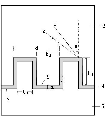
[0054] The material of the grating layer 3 is fused silica optical glass, and the material of the dielectric layer 4 is TiO 2 , the metal reflection layer 5 is silver, the period d of the grating layer 3 is 690 nanometers, the groove depth of the grating layer 3 and the period ratio h are 0.8, the duty ratio f of the grating layer 3 is 0.3, and the duty ratio of the metal reflection layer 5 is t is 0.37. The incident angle θ of the incident light in the grating layer 3 is 47°.

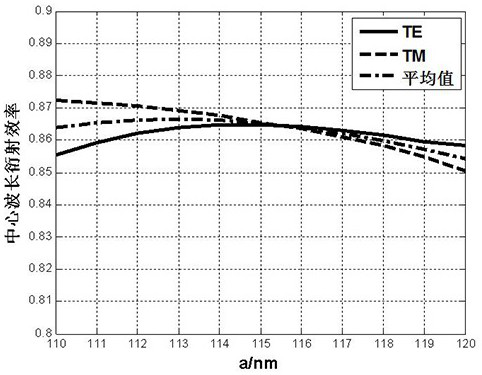
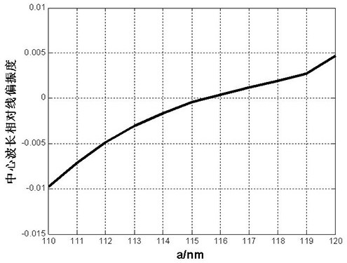
[0055] see figure 2 Shown is the variation curve of the average diffraction efficiency at the central wavelength of the working band with the thickness a of the dielectric layer 4 . image 3 is the variation curve of the relative degree of linear polarization DP at the central wavelength of the working band with the thickness a of the dielectric layer 4; figure 2 and image 3 It can be seen that when the thickness a of the dielectric layer is 115 nm, the immersion grating has better diffraction e...

Embodiment 2

[0058] The material of the grating layer 3 is fused silica optical glass, and the dielectric layer 4 is Al 2 o 3 , the metal reflective layer 5 is silver, the period d of the grating layer 3 is 690 nanometers, the groove depth to period ratio h of the grating layer 3 is 0.8, and the duty cycle t of the metal reflective layer 5 is 0.2. The incident angle θ of the incident light in the grating layer 3 is 48°.

[0059] Figure 5 It is the variation trend of the average diffraction efficiency at the central wavelength of the working band with the thickness a of the dielectric layer 4 and the duty ratio f of the grating layer 3 in embodiment two; The variation trend of the thickness a of the layer 4 and the duty ratio f of the grating layer 3, the colors in the figure indicate the average diffraction efficiency and the relative linear polarization degree. combine Figure 5 and Figure 6 As shown, it can be seen that the duty ratio f of the grating layer 3 is 0.2, the thickness...

Embodiment 3

[0062] The material of the grating layer 3 is fused silica optical glass, and the dielectric layer 4 is TiO 2 , the metal reflection layer 5 is silver, the period d of the grating layer 3 is 1010 nanometers, the ratio h of the groove depth to the period of the grating layer 3 is 0.8, and the duty ratio t of the metal reflection layer 5 is 0.4. The incident angle θ of the incident light in the grating layer 3 is 43°.

[0063] Fig. 8 is the variation trend of the average diffraction efficiency at the central wavelength of the working band with the thickness a of the dielectric layer 4 and the duty cycle f of the grating layer 3 in embodiment three; the relative degree of linear polarization DP at the central wavelength of Fig. 9 varies with the dielectric layer The variation trend of the thickness a of 4 and the duty ratio f of the grating layer 3, the colors in the figure indicate the average diffraction efficiency and the relative degree of linear polarization. combine Figu...


PUM

PropertyMeasurementUnit
thicknessaaaaaaaaaa
angle of incidenceaaaaaaaaaa
wavelengthaaaaaaaaaa

Abstract

The invention discloses a low-polarization high-diffraction-efficiency metal reflection immersion grating and an optical system. The grating comprises: a grating layer, wherein the grating layer comprises a plurality of first groove bodies arranged in an array manner; a dielectric layer covering the surface of the grating layer at equal thickness, wherein the thickness of the dielectric layer is smaller than the groove depth of the grating layer, and a second groove body is formed in the surface of the dielectric layer; and a metal reflection layer located on the side, away from the grating layer, of the dielectric layer, wherein the second groove body is filled with one side of the metal reflection layer, a first interface is formed between the grating layer and the dielectric layer, a second interface is formed between the dielectric layer and the metal reflection layer, incident light enters towards the direction of the first interface through the interior of the grating layer, a diffraction effect occurs among the first interface, the dielectric layer and the second interface to generate diffracted light, and the diffracted light is reflected by the metal reflection layer and exits from the interior of the grating layer. According to the invention, low polarization and high diffraction efficiency can be realized, the manufacturing process difficulty is reduced, and the low-polarization high-diffraction-efficiency metal reflection immersion grating has important application value in the field of high-resolution atmospheric detection.

Description

technical field [0001] The invention relates to the technical field of gratings, in particular to a metal reflective immersion grating with low polarization and high diffraction efficiency and an optical system. Background technique [0002] In grating-type hyperspectral imaging instruments, especially for spectrometers used to detect atmospheric components, the grating with the characteristics of low polarization, high diffraction efficiency, and high dispersion is one of the core components for the instrument to achieve high-precision detection and inversion. As the spectral resolution requirements of the instrument increase, the volume and mass of the system increase dramatically. E. Hulthén proposed the concept of immersion grating (see E. Hulthén, and H. Neuhaus, Nature, 1954, 173(4401):442-443.), when the grating surface is immersed in a medium with a refractive index n, its spectrum The resolving power is increased by n times than that without immersion. This means ...

Claims


Application Information

Patent Timeline
Patent Type & Authority Applications(China)
IPC IPC(8): G02B5/18
CPCG02B5/1861
Inventor 潘俏沈为民
Owner SUZHOU UNIV
Features
  • Generate Ideas
  • Intellectual Property
  • Life Sciences
  • Materials
  • Tech Scout
  • Unparalleled Data Quality
  • Higher Quality Content
  • 60% Fewer Hallucinations
Learn More