Landslide stress cracking type monitoring system applied to mountainous road

A landslide and monitoring system technology, applied in the direction of measuring devices, soil material testing, material inspection products, etc., can solve the problems of difficult practical application, monitoring false alarms, and high difficulty, so as to easily trigger alarms, reduce friction, and improve success sexual effect

Inactive Publication Date: 2020-09-25
杭州翼兔网络科技有限公司
View PDF0 Cites 3 Cited by
  • Summary
  • Abstract
  • Description
  • Claims
  • Application Information

AI Technical Summary

Problems solved by technology

[0005] At present, among the technical methods used for landslide monitoring, manual measurement technology not only has a low degree of automation, but also has too much labor, and it is difficult to achieve long-term real-time measurement
The existing main monitoring technologies are described as follows: (1) Image recognition technology, although it solves the problem of real-time dynamic monitoring, the accuracy of intelligent image recognition decreases under severe weather conditions such as rain, snow, fog, and monitoring false alarms occur from time to time. Even in the event of a dangerous situation, it was missed
Replacing intelligent image recognition with artificial observation images is only a short-term expedient measure. 24-hour uninterrupted observation is difficult to last. In addition, the high cost of the image monitoring system also makes it difficult for this technology to be widely used; (2) Pull wire displacement monitoring, the theory of this method It is simple in appearance, but limited by the geographical environment, the ...

Method used


Image

  • Landslide stress cracking type monitoring system applied to mountainous road
  • Landslide stress cracking type monitoring system applied to mountainous road
  • Landslide stress cracking type monitoring system applied to mountainous road

Examples


Embodiment 1

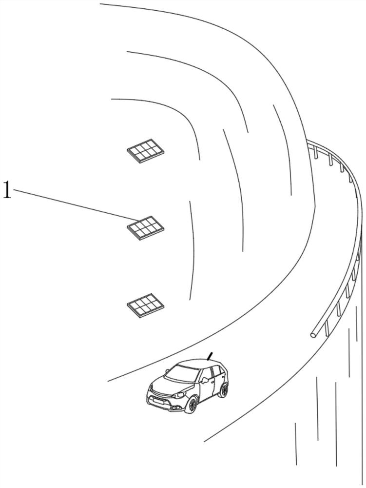
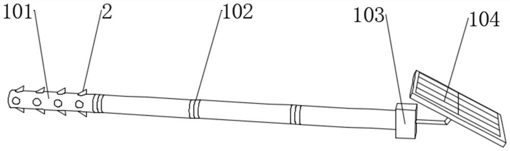
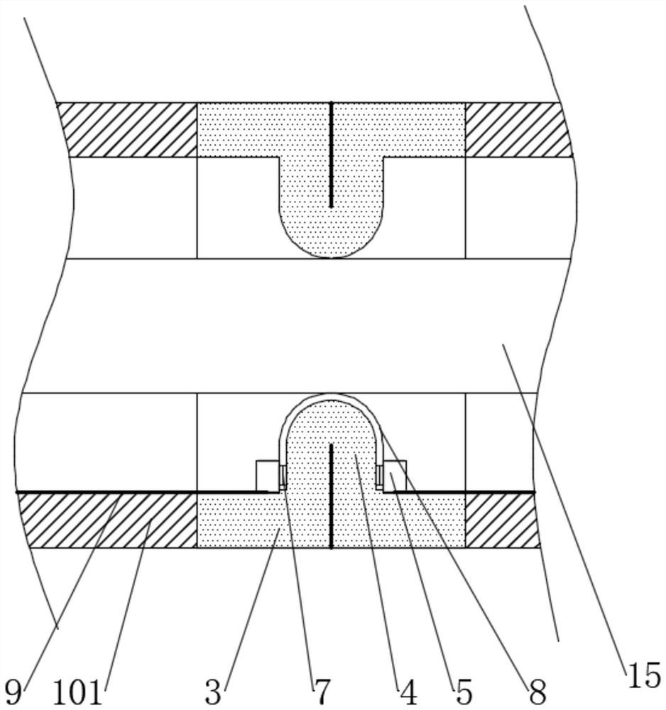
[0035] see Figure 1-2 , a landslide cracking monitoring system applied to mountain roads, including a pre-embedded monitoring module, the pre-buried detection module includes a base station and a plurality of crack monitoring rods 1, the diameter of the crack monitoring rod 1 is 10cm, and the length is 5m , the length of the main body 101 is 1m, and the crack monitoring rods 1 are pre-buried in the mountain body, and the crack monitoring rods 1 extend to the outside of the mountain. The embedding distance of the crack monitoring rods 1 is divided into horizontal direction and vertical direction. The distance in the horizontal direction should be 40-50m, and the distance in the vertical direction should be 10-15m. Under the premise of reducing the monitoring cost, the mountain can be fully covered and a tight monitoring network can be formed. It can be detected in time, and is especially suitable for mountainous areas. The crack monitoring rod 1 includes a plurality of main pa...


PUM

PropertyMeasurementUnit
Lengthaaaaaaaaaa
Diameteraaaaaaaaaa
Lengthaaaaaaaaaa

Abstract

The invention discloses a landslide stress cracking type monitoring system applied to mountain roads. A landslide monitoring network for a mountain body can be formed by embedding and inserting the stress crack monitoring rods. The system is based on the characteristic that landslide cracks horizontally and then slides down vertically. Through tensile force of mountain soil layer cracking, the cracking part of the cracking detection rod is stretched, and early warning of the landslide is realized by taking the result as a triggering condition. Meanwhile, the severity degree of the landslide can be judged according to the cracking part. Subsequent targeted preparation of rescue and emergency work is facilitated. On one hand, information is sent to a cloud platform server for a remote monitoring center to quickly know, on the other hand, an alarm is given in real time to remind passing vehicles. The system is simple to erect and low in cost, the traditional power supply problem is solvedby collecting solar energy and converting the solar energy into electric energy, the system is not limited by the geographical environment, the monitoring work amount is small, the monitoring difficulty is low, unmanned intelligent automatic monitoring is achieved, the safety degree is high, and early warning is timely.

Description

technical field [0001] The invention relates to the technical field of highways, and more specifically relates to a landslide response-crack monitoring system applied to mountainous highways. Background technique [0002] Mountainous roads refer to roads located in mountainous areas with circuitous routes, large vertical slopes, and many special structures. According to the area traveled by the route, it can be divided into roads along the river (stream), roads on the mountainside, roads on the ridge and roads across the ridge. Its roadbed is often filled with high height and excavated deeply, and tunnels or viaducts are used to cross special difficult places. Landslides and landslides are prone to occur, and the construction and maintenance costs are relatively high. [0003] Landslide refers to the soil or rock mass on the slope, affected by factors such as river scouring, groundwater activity, rainwater immersion, earthquake and artificial slope cutting, under the actio...

Claims


Application Information

Patent Timeline
IPC IPC(8): G08B21/10G01N33/24G01B21/32
CPCG01B21/32G01N33/24G08B21/10
Inventor 徐承迪
Owner 杭州翼兔网络科技有限公司
Why Eureka
Try Eureka