
Gypsum cutting tool for orthopedics department

A cutting tool and gypsum technology, applied in the field of orthopedic gypsum cutting tools, can solve the problems of inconvenient use, reduced work efficiency, time-consuming and labor-intensive problems, and achieve the effect of ensuring protection and improving cutting efficiency

Inactive Publication Date: 2020-09-29
李冰冰
View PDF1 Cites 2 Cited by
  • Summary
  • Abstract
  • Description
  • Claims
  • Application Information

AI Technical Summary

Problems solved by technology

But when cutting, because the patient is in a state of high tension, it is easy to move, and then it will also cause the patient's skin to be cut; for this reason, people propose a plaster cutting device, such as a kind of orthopedic device disclosed in Chinese patent CN110916906A. The gypsum cutting device for treatment includes a workbench, on which a chute is slidably connected with a cutting knife driven by a motor, and also includes a slider slidably connected in the chute, and the edge of the cutting knife is perpendicular to the chute The direction of sliding is connected to the slider, and the slider is provided with an infrared detector and a controller for controlling the sliding of the cutting knife; the invention solves the problem that the patient suffers from mental stress and stress response when cutting plaster in the prior art. , it will move, and then there will be contact with the cutting knife, causing the problem of skin injury;
[0003] However, in actual use, the use of cutters, suction cups, and airbags is complicated, time-consuming and labor-intensive, requiring doctors to have skilled operating experience, and the workbench is not convenient enough to fix the plaster to be cut, which reduces work efficiency. , causing inconvenience to use

Method used

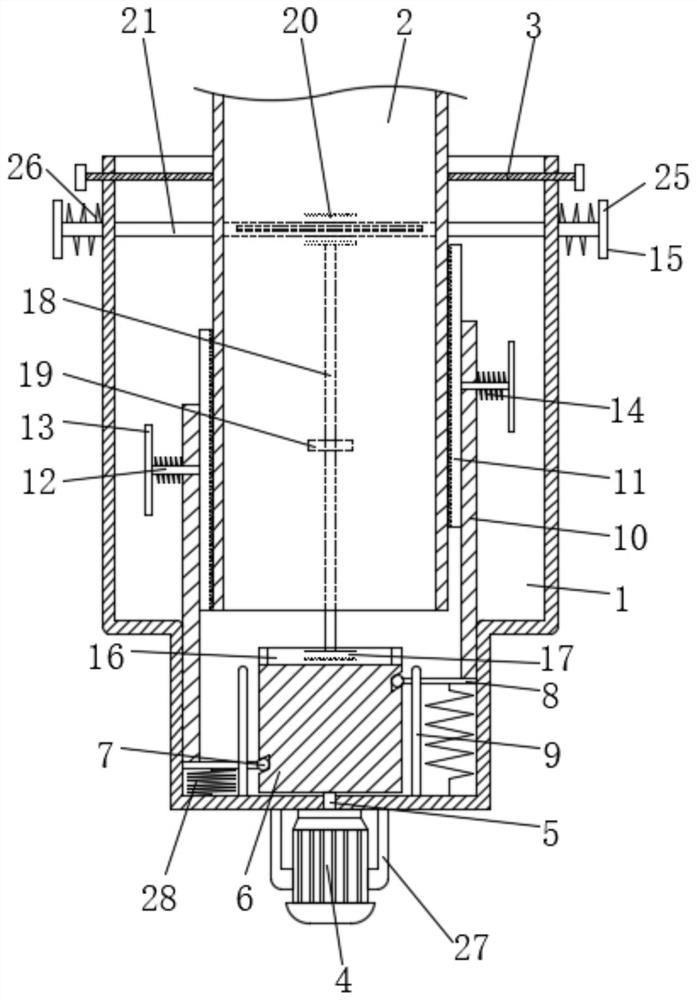
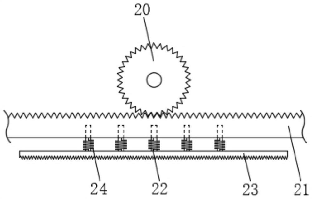

Image

  • Gypsum cutting tool for orthopedics department
  • Gypsum cutting tool for orthopedics department
  • Gypsum cutting tool for orthopedics department

Examples


Embodiment Construction

[0026] The following will clearly and completely describe the technical solutions in the embodiments of the present invention with reference to the accompanying drawings in the embodiments of the present invention. Obviously, the described embodiments are only some, not all, embodiments of the present invention. Based on the embodiments of the present invention, all other embodiments obtained by persons of ordinary skill in the art without making creative efforts belong to the protection scope of the present invention.

[0027] see Figure 1 to Figure 4 , the present invention provides a technical solution: a plaster cutting tool for orthopedics, including a sleeve 1, the sleeve 1 is provided with a gypsum 2 to be cut, and the gypsum 2 to be cut is placed in the sleeve 1 through the patient's limb , taking plaster 2 to be cut at the arm as an example;

[0028] Both sides of the sleeve 1 close to the top are provided with screw holes and are screwed with bolts 3 through the sc...


PUM


Abstract

The invention discloses a gypsum cutting tool for orthopedics department. A sleeve is internally provided with gypsum to be cut, screw holes are formed in the two sides, close to the top, of the sleeve, bolts are connected through the screw holes in a screwed mode, the opposite ends of the two bolts are movably connected with the side face of the gypsum to be cut, a motor is fixedly connected withthe bottom of the sleeve, a rotating shaft is fixedly connected with the top of an output shaft of the motor, the surface of the rotating shaft penetrates through the sleeve and is rotatably connected with the sleeve, a cylindrical cam is fixedly connected with the top of the rotating shaft, and a sliding block is slidably connected with the inner wall of an outer contour sliding groove of the cylindrical cam. According to the gypsum cutting tool, through the cooperative use between the structures, the problems that in the actual use process, because a cutting knife, a sucker and an air bag are complex in use, time and labor are wasted, a physician is required to have a skilled operation experience, the gypsum to be cut is not convenient to fix by a workbench, the working efficiency is reduced, and inconvenience is brought to use are solved.

Description

technical field [0001] The invention relates to the technical field of medical equipment, in particular to a plaster cutting tool for orthopedics. Background technique [0002] In orthopedic treatment, in order to fix the affected part of the patient and promote the normal healing of the bones, it is usually necessary to put plaster on the affected part of the patient to keep the limbs fixed. After the patient's affected area has healed, the cast will need to be removed. The traditional method is to use a manual cutter to cut out the gap in the plaster, and then break the plaster into pieces. In this method, the operator controls the cutting depth. If the control is not good, the patient's skin may be injured. Therefore, a kind of plaster cutting device has occurred, which can keep the cutting knife stable and reduce the situation of cutting the patient's skin. But when cutting, because the patient is in a state of high tension, it is easy to move, and then it will also ca...

Claims


Application Information

Patent Timeline
Patent Type & Authority Applications(China)
IPC IPC(8): B28D1/06B28D7/00B28D7/04A61F5/05
CPCA61F5/05B28D1/068B28D7/00B28D7/005B28D7/04
Inventor 李冰冰李晓洁
Owner 李冰冰
Learn More