Prefabricated part, prefabricated part mold, wind power blade and manufacturing method of wind power blade
A technology of prefabricated parts and molds, which is applied in the manufacture of wind power blades and wind power blades, prefabricated part molds, and prefabricated parts. Molding rate, the effect of improving the pouring effect
- Summary
- Abstract
- Description
- Claims
- Application Information
AI Technical Summary
Problems solved by technology
Method used
Image
Examples
Embodiment 1
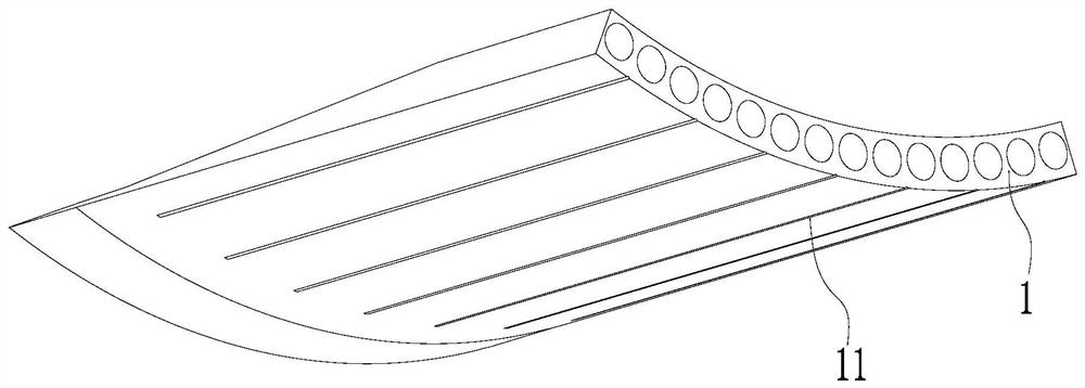
[0039] Please also refer to Figure 1 to Figure 4 , the preform provided by the present invention is now described. The preform includes a body 1 . The prefabricated part is generally a fiber-reinforced composite material formed by at least fiber material and resin material. It is formed by heating or curing at room temperature. The prefabricated part can be a blade root prefabricated part with a curved surface, a beam prefabricated part, a web The shape and size of the body 1 of the skin prefabricated part or the prefabricated part of other parts can be adjusted according to the specific prefabricated shape. The fiber material can be one or a combination of glass fiber, carbon fiber, wood fiber, synthetic fiber, etc., and the resin material is also a perfusion material, which can be one or a combination of thermosetting or thermoplastic materials such as epoxy resin and polyester. The blade root prefabricated part may also include bolt connection parts (such as bolt sleeves...
Embodiment 2
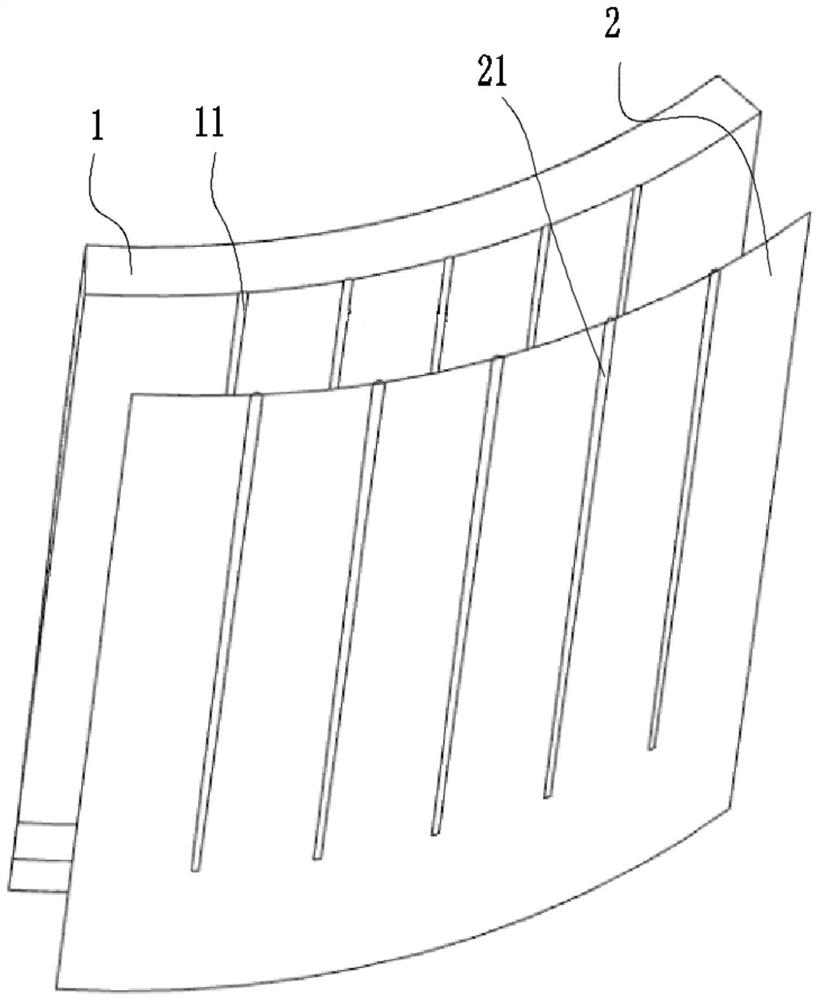
[0052] Please also refer to Figure 1 to Figure 4 , the preform mold provided by the present invention is now described. The preform mold includes a mold 2, the mold 2 has an upper surface and a lower surface, wherein the main surface of the mold 2 generally refers to the upper surface of the mold 2, and the upper surface of the mold 2 is processed and shaped to adapt to the preform The profile of the lower surface, that is, different prefabricated parts correspond to different molds 2, and the shape of the upper surface of the mold 2 can be prefabricated into different shapes according to different prefabricated parts, for example, the prefabricated part can be a blade root prefabricated part with an arc surface , the upper surface of the mold 2 is a curved surface.
[0053] The upper surface of the mold 2 is protruded with a raised portion 21 for forming the strip-shaped groove, and the raised portion 21 extends from one end of the mold 2 toward the other end of the mold 2 ...
Embodiment 3
[0062] Please also refer to Figure 1 to Figure 6 , the method for manufacturing the preform provided by the present invention will now be described. The manufacturing method of described preform comprises the steps:
[0063] S101, laying the lower layer material on the preform mold as described in embodiment 2, and laying a vacuum bag on the lower layer material;
[0064] Among them, the material of the lower layer generally includes a reinforcing material layer, a compensation layer, a release cloth and a flow guide system. Among them, the reinforcing material layer is generally a glass fiber cloth layer or a carbon fiber cloth layer or a mixed fiber material cloth layer. 1 to 3 layers, the compensation layer is generally preferably selected as a biaxial layer, and the release cloth and the guide cloth are generally the release cloth and the guide cloth commonly used in the prior art. Of course, according to the actual situation and specific needs, the compensation layer o...
PUM
| Property | Measurement | Unit |
|---|---|---|
| depth | aaaaa | aaaaa |
| width | aaaaa | aaaaa |
| thickness | aaaaa | aaaaa |
Abstract
Description
Claims
Application Information
 - R&D
- Intellectual Property
- Life Sciences
- Materials
- Tech Scout
- Unparalleled Data Quality
- Higher Quality Content
- 60% Fewer Hallucinations
Browse by: Latest US Patents, China's latest patents, Technical Efficacy Thesaurus, Application Domain, Technology Topic, Popular Technical Reports.
© 2025 PatSnap. All rights reserved.Legal|Privacy policy|Modern Slavery Act Transparency Statement|Sitemap|About US| Contact US: help@patsnap.com


