Electric scanning antenna

An antenna and electric scanning technology, which is applied in the direction of electric short antenna, antenna, antenna coupling, etc., can solve the problems of small beam coverage and reduce the ability of electric scanning antenna to send and receive signals, so as to improve the ability of antenna to send and receive signals, improve the ability of sending and receiving signals, etc. The ability of the signal, the effect of increasing the working bandwidth

Active Publication Date: 2020-09-29
ANHUI SUN CREATE ELECTRONICS
View PDF9 Cites 1 Cited by
  • Summary
  • Abstract
  • Description
  • Claims
  • Application Information

AI Technical Summary

Problems solved by technology

[0003] The beam coverage of the existing electronically scanned antenna is small, and it is impossible to achieve omnidirectional coverage of the signal, thereby reducing the ability of the electronically scanned antenna to send and receive signals

Method used


Image

  • Electric scanning antenna
  • Electric scanning antenna
  • Electric scanning antenna

Examples


Embodiment

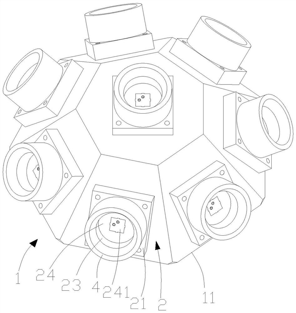
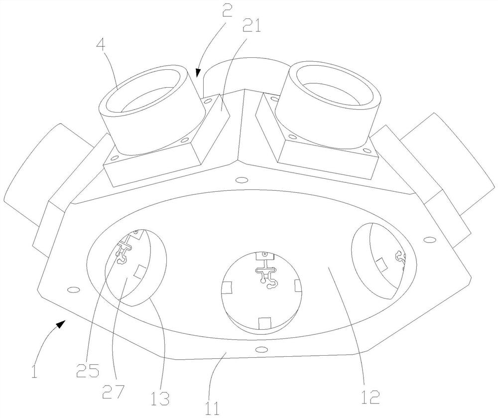
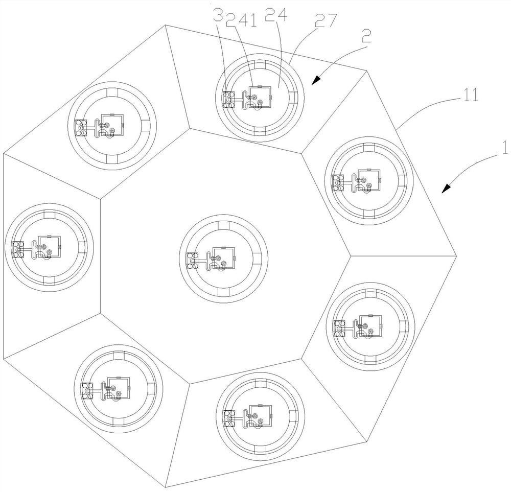
[0051]An electric scanning antenna includes an antenna base 1 and a radiation unit 2 for transmitting signals. The antenna base 1 includes an upper top surface and a slope extending downward from the upper top surface. In this embodiment, the antenna base 1 is Prismatic or circular frustum, such as figure 1 , figure 2 and image 3 As shown, the radiation unit 2 is arranged on the upper top surface and the peripheral side of the antenna base 1 .

[0052] like figure 1 and figure 2 As shown, the antenna base 1 includes a base body 11 , a cavity 12 inside the base body 11 and a through hole 13 provided on the inner wall of the cavity 12 . In this embodiment, the base body 11 is a heptagonal prism, and the number of radiation units 2 is eight, and the radiation units 2 are respectively distributed on the seven side surfaces and the upper bottom surface of the base body 11 . The opening of the cavity 12 is disposed on the lower bottom surface of the base body 11 .

[0053] ...


PUM


Abstract

The invention relates to the field of antennas and particularly relates to an electric scanning antenna. The antenna comprises an antenna base and a radiation unit used for transmitting signals, wherein the radiation unit is arranged on an upper top surface of the antenna base and a slope surface extending downwards from the upper top surface, and the radiation units of the planar electric scanning antenna for signal transmission are located on the same plane. The antenna is advantaged in that the radiation units are distributed on the prismoid-shaped or circular-truncated-cone-shaped antennabase, so the radiation units form the three-dimensional electric scanning antenna, and the signal coverage range of the three-dimensional electric scanning antenna is larger than that of the planar electric scanning antenna.

Description

technical field [0001] The invention relates to the field of antennas, in particular to an electric scanning antenna. Background technique [0002] As a component used to transmit or receive radio waves, the antenna plays a pivotal role in the wireless communication system and is an indispensable part of the wireless communication system. With the rapid development of high-frequency satellite communication systems, radar, wireless communication systems, especially the construction of global 4G and 5G networks, the requirements for antennas are also getting higher and higher. It is precisely because of this demand that various types of electronically scanned antennas have flourished. [0003] The beam coverage of the existing electronically scanned antenna is small, and omnidirectional signal coverage cannot be achieved, thereby reducing the ability of the electronically scanned antenna to transmit and receive signals. Contents of the invention [0004] In order to solve ...

Claims


Application Information

Patent Timeline
IPC IPC(8): H01Q1/36H01Q1/12H01Q9/04H01Q1/50H01Q13/02H01Q1/00H01Q21/00H01Q1/52H01Q1/22H01Q23/00
CPCH01Q1/36H01Q1/12H01Q9/0428H01Q1/50H01Q13/02H01Q1/002H01Q21/0006H01Q1/521H01Q1/22H01Q23/00
Inventor 李霞孙浩高静胡卫东
Owner ANHUI SUN CREATE ELECTRONICS
Why Eureka
Try Eureka