Steel strip coil stock on-line shearing welding machine

A technology for welding machines and steel strip coils, which is applied to metal processing machinery parts, clamping, support, etc., and can solve problems such as affecting the quality of coil connection, large tolerance deviation, and plate warping

Active Publication Date: 2020-10-02
JUNJIE MACHINERY SHENZHEN
View PDF15 Cites 6 Cited by
  • Summary
  • Abstract
  • Description
  • Claims
  • Application Information

AI Technical Summary

Problems solved by technology

[0002] In the prior art, in the electroplating copper production line of low-carbon steel thin plate coils, the steel strips are generally conveyed vertically. When changing and connecting coils, the steel strips need to be twisted to Horizontal state, and then manually cut the head and tail of the front and rear two coils of steel strip, and then weld and fix it. The cutting and welding time is as long as 5 minutes. Not only the process is complicated, but also the efficiency is low. At the same time, there will be When the plate is tilted, it is difficult to ensure the alignment of the end and the end, and the tolerance deviation is large
In addition, during welding, the vertical steel strip needs to be twisted into a horizontal state for spot welding. The twisted steel strip is easily deformed, which in turn affects the connection quality of the front and rear coils
Especially in the process of shearing and welding, the strength and risk of manual operation are relatively high. During the welding operation, the beryllium fronts on both sides of the steel strip are likely to scratch the hands, so there are potential safety hazards and lack of automatic processing capabilities. The uneven surface will also affect the processing effect of the next copper plating process, making it difficult to meet production requirements

Method used


Image

  • Steel strip coil stock on-line shearing welding machine
  • Steel strip coil stock on-line shearing welding machine
  • Steel strip coil stock on-line shearing welding machine

Examples


Embodiment Construction

[0021] The present invention will be described in more detail below in conjunction with the accompanying drawings and embodiments.

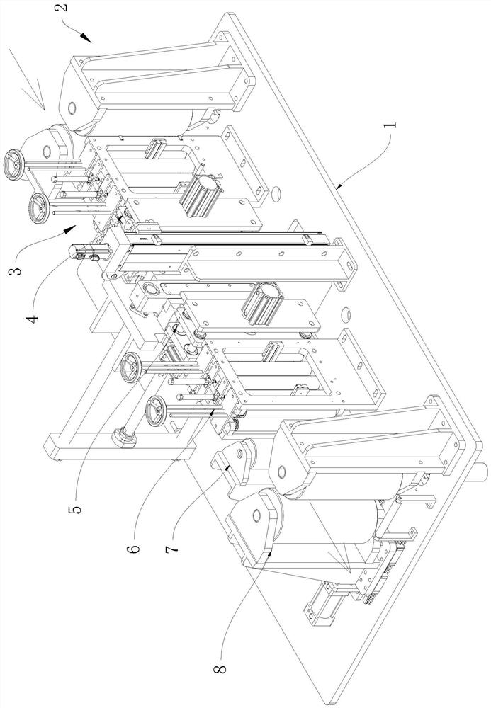
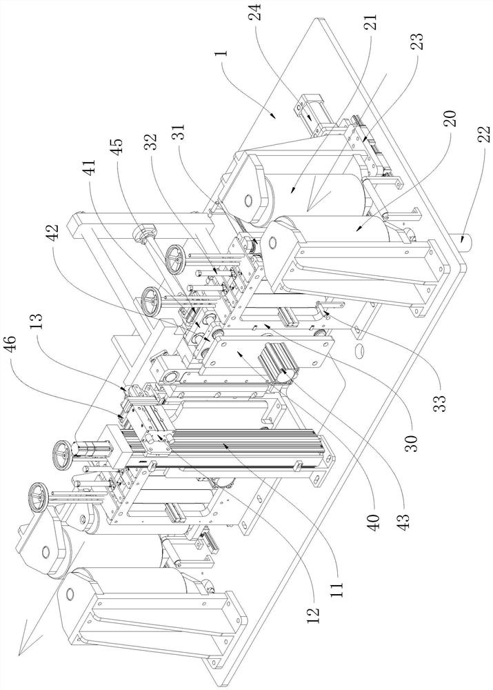
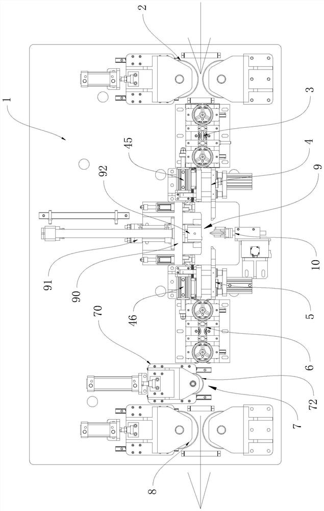
[0022] The invention discloses an on-line shear welding machine for steel strip coils, which combines Figure 1 to Figure 5 As shown, it includes an organic platform 1, and the said platform 1 is provided with:

[0023] A conveying mechanism 2 at the feeding end, which is used to apply a traction force to the rear rolled steel strip in an upright state, and then drive the rear rolled steel strip to be conveyed into the machine 1;

[0024] A feeding end nip roller assembly 3 is located on the output side of the feeding end conveying mechanism 2, and the feeding end nip roller assembly 3 is used for the rear end of the feeding conveying mechanism 2 output side Rolled steel strip exerts preset pressure;

[0025] A feeding end clamping mechanism 4 is located on the output side of the feeding end nip roller assembly 3, and the feeding end clamping m...


PUM


Abstract

The invention discloses a steel strip coil stock on-line shearing welding machine. The steel strip coil stock on-line shearing welding machine comprises a machine table, and the machine table is provided with a feeding end conveying mechanism used for driving a rear coil steel strip to be conveyed into the machine table, a feeding end material pressing roller assembly used for applying preset pressure to the rear coiled steel strip, a feeding end material clamping mechanism used for clamping the rear coil steel strip, a discharging end material clamping mechanism used for clamping a front coilsteel strip, a discharging end material pressing roller assembly used for applying preset pressure to the front coil steel strip, a material storage mechanism used for applying lateral pressure to the front coiled steel strip, a discharging end conveying mechanism used for driving the front coiled steel strip to be conveyed out of the machine table, a shearing mechanism used for shearing the tailend of the front coiled steel strip and the front end of the rear coiled steel strip, and a welding mechanism used for welding the tail end of the front coiled steel strip and the front end of the rear coiled steel strip, so that the front coiled steel strip and the rear coiled steel strip are in butt joint in sequence. According to the steel strip coil stock on-line shearing welding machine, shearing and welding can be automatically completed, labor can be saved, the machining efficiency can be improved, potential safety hazards are reduced, and the machining quality is improved.

Description

technical field [0001] The invention relates to low-carbon steel coil material processing equipment for an electroplating copper production line, in particular to an on-line shear welding machine for steel coil material. Background technique [0002] In the prior art, in the electroplating copper production line of low-carbon steel thin plate coils, the steel strips are generally conveyed vertically. When changing and connecting coils, the steel strips need to be twisted to Horizontal state, and then manually cut the head and tail of the front and rear two coils of steel strip, and then weld and fix it. The cutting and welding time is as long as 5 minutes. Not only the process is complicated, but also the efficiency is low. At the same time, there will be When the plate is tilted, it is difficult to ensure the alignment of the end and the end, and the tolerance deviation is large. In addition, during welding, the vertical steel strip needs to be twisted into a horizontal st...

Claims


Application Information

Patent Timeline
Patent Type & Authority Applications(China)
IPC IPC(8): B23P23/04B23Q3/08B23Q7/00
CPCB23P23/04B23Q3/08B23Q7/00
Inventor 李伯仲邱焕元
Owner JUNJIE MACHINERY SHENZHEN
Why Eureka
Try Eureka