An on-line shear welding machine for steel strip coils

A welding machine and steel coil technology, which is used in metal processing machinery parts, manufacturing tools, and other manufacturing equipment/tools, etc., can solve the problems of large tolerance deviations, complicated procedures, and difficulty in ensuring end-to-end alignment.

Active Publication Date: 2022-03-18
JUNJIE MACHINERY SHENZHEN
View PDF15 Cites 1 Cited by
  • Summary
  • Abstract
  • Description
  • Claims
  • Application Information

AI Technical Summary

Problems solved by technology

[0002] In the prior art, in the electroplating copper production line of low-carbon steel thin plate coils, the steel strips are generally conveyed vertically. When changing and connecting coils, the steel strips need to be twisted to Horizontal state, and then manually cut the head and tail of the front and rear two coils of steel strip, and then weld and fix it. The cutting and welding time is as long as 5 minutes. Not only the process is complicated, but also the efficiency is low. At the same time, there will be When the plate is tilted, it is difficult to ensure the alignment of the end and the end, and the tolerance deviation is large
In addition, during welding, the vertical steel strip needs to be twisted into a horizontal state for spot welding. The twisted steel strip is easily deformed, which in turn affects the connection quality of the front and rear coils
Especially in the process of shearing and welding, the strength and risk of manual operation are relatively high. During the welding operation, the beryllium fronts on both sides of the steel strip are likely to scratch the hands, so there are potential safety hazards and lack of automatic processing capabilities. The uneven surface will also affect the processing effect of the next copper plating process, making it difficult to meet production requirements

Method used


Image

  • An on-line shear welding machine for steel strip coils
  • An on-line shear welding machine for steel strip coils
  • An on-line shear welding machine for steel strip coils

Examples


Embodiment Construction

[0021] The present invention will be described in more detail below with reference to the accompanying drawings and examples.

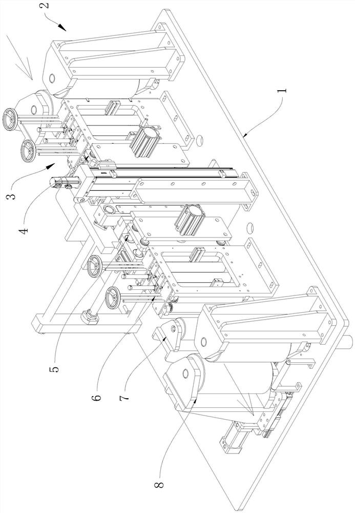
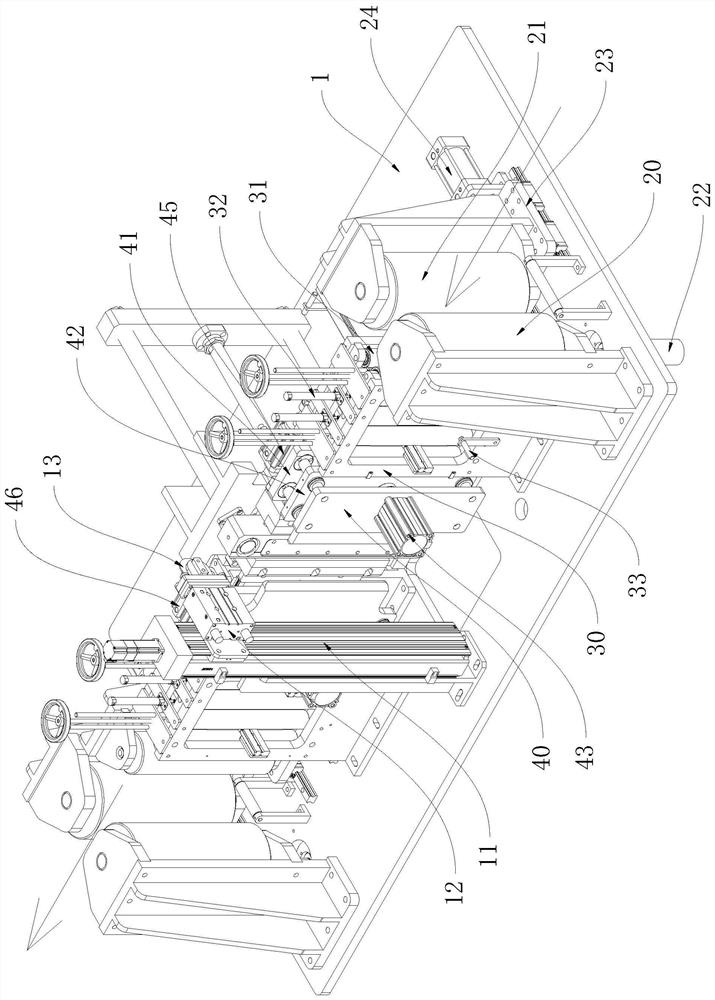
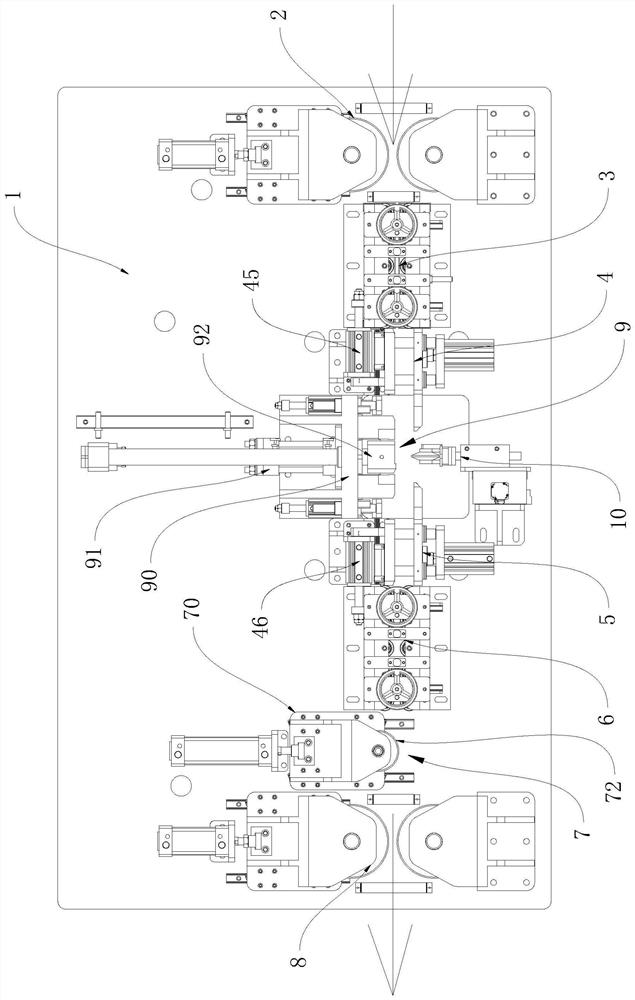
[0022] The present invention discloses a steel strip coil online shear welding machine, a combination Figure 1 to 5 As shown, it includes an organic table 1, and the machine is provided:

[0023] One upper material conveying mechanism 2, is used to apply a traction force to the rear roller strip of the upright state, and then drive the rear volume steel band to the meter 1;

[0024] The upper material end pressing roller assembly 3 is provided on the output side of the upper feed end conveying mechanism 2, and the upper material end pressure roller assembly 3 is used to output the output side of the upper delivery mechanism 2. Roll steel strips apply preset pressure;

[0025] An upper material is provided on the output side of the upper material end pressing roller assembly 3, which is used to output the upper pin press roller assembly 3. The rear volume ...


PUM


Abstract

The invention discloses an on-line shear welding machine for steel strip coils, which comprises an organic platform, on which there is a conveying mechanism at the feeding end, which is used to drive the coiled steel strip to be transported into the machine platform; The roller assembly is used to exert preset pressure on the rear coiled steel strip; the clamping mechanism at the feeding end is used to clamp the rear coiled steel strip; the clamping mechanism at the unloading end is used to clamp the front coiled steel strip; the blanking The end pressure roller assembly is used to apply preset pressure to the front coiled steel strip; the material storage mechanism is used to apply lateral pressure to the front coiled steel strip; the feeding mechanism at the feeding end is used to drive the front coiled steel strip to the machine table External conveying; shearing mechanism, used to cut the end of the front coil steel strip and the front end of the rear coil steel strip; welding mechanism, used to weld the end of the front coil steel strip and the front end of the rear coil steel strip, to Make the front coiled steel belt and the rear coiled steel belt sequentially butt. The invention can automatically complete cutting and welding, can save labor, can improve processing efficiency, reduce potential safety hazards and improve processing quality.

Description

Technical field [0001] The present invention relates to a low-carbon steel coil processing apparatus for electroplated copper production lines, and more particularly to a steel strip coil online shear welding machine. Background technique [0002] In the prior art, in the electroplated copper production line of low-carbon steel sheet, the steel strip is generally vertically transmitted, and the coil and the cloth are changed, and when the steel belt is required to turn the steel belt after the stop. The horizontal state, then use the first tail of the front and rear two rolls of steel strips, then weld, cut, the welding time is 5 min, not only the process is complicated, but also low efficiency, while in the spot welding process The situation of the sheet is difficult to ensure that the end is aligned, the tolerance is large. Further, when welding is performed, it is necessary to turn the vertically steel strip to the horizontal state to perform spot welding, and the twisted stee...

Claims


Application Information

Patent Timeline
Patent Type & Authority Patents(China)
IPC IPC(8): B23P23/04B23Q3/08B23Q7/00
CPCB23P23/04B23Q3/08B23Q7/00
Inventor 李伯仲邱焕元
Owner JUNJIE MACHINERY SHENZHEN
Why Eureka
Try Eureka