
Concrete-filled steel tube pile structure and construction method thereof

A technology of steel pipe concrete piles and steel pipe piles, which can be applied to foundation structure engineering, sheet pile walls, buildings, etc., can solve the problems of reduced bearing capacity, decreased load capacity, uneven thickness of concrete, etc., and achieve the effect of enhanced bearing capacity

Active Publication Date: 2020-10-02
SICHUAN DEPT OF TRANSPORTATION HIGHWAY PLANNING PROSPECTING & DESIGN RES INST
View PDF8 Cites 13 Cited by
  • Summary
  • Abstract
  • Description
  • Claims
  • Application Information

AI Technical Summary

Problems solved by technology

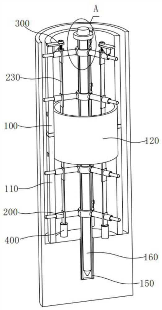
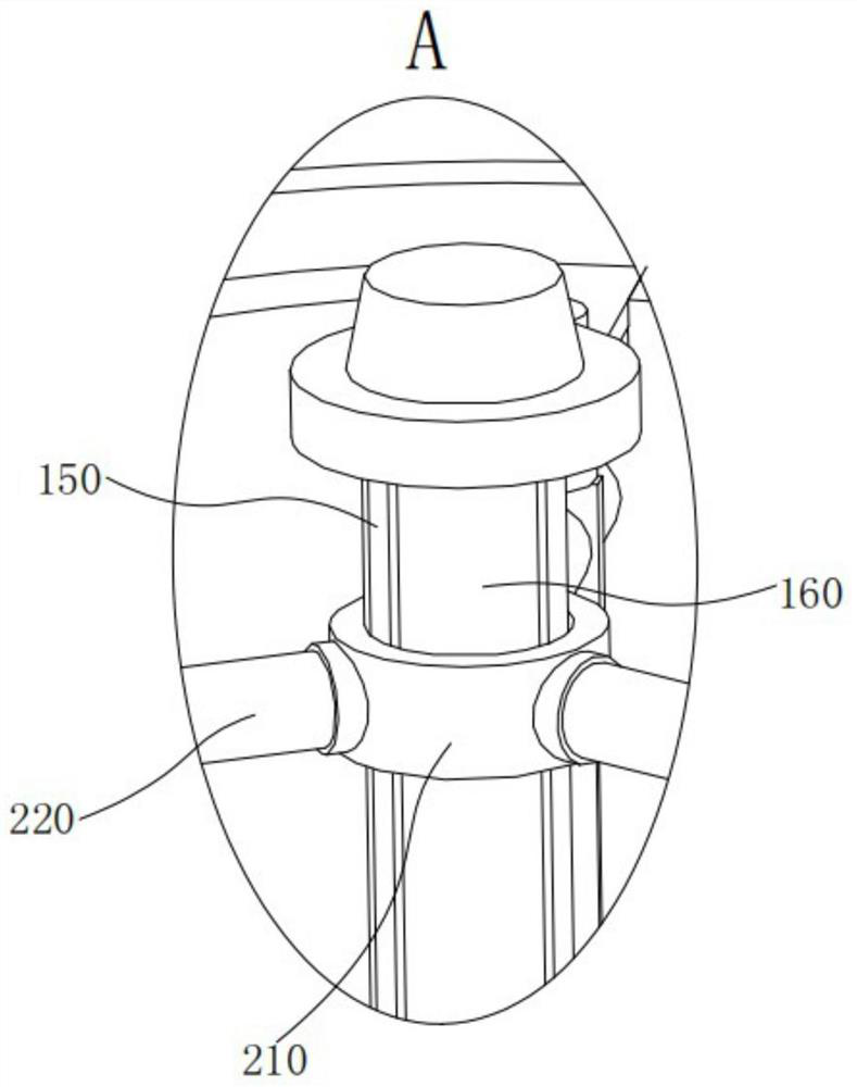
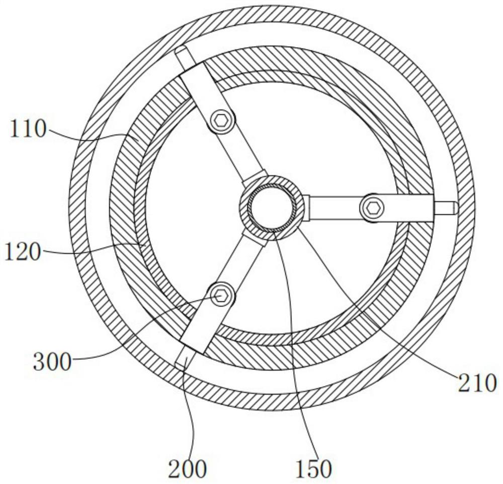
[0004] In order to make up for the above deficiencies, the present invention provides a steel pipe concrete pile structure, which aims to improve the eccentricity of the bottom hole when the steel pipe is installed, resulting in the uneven thickness of the concrete poured between the bottom hole and the steel pipe in the later stage, and the bearing capacity is greatly reduced. The ground is not vertical, further causing the problem of load drop

Method used


Image

  • Concrete-filled steel tube pile structure and construction method thereof
  • Concrete-filled steel tube pile structure and construction method thereof
  • Concrete-filled steel tube pile structure and construction method thereof

Examples


Embodiment

[0047] At present, during the construction of steel pipe concrete piles, a tripod and a locator are usually first laid on the pipe pins of the steel pipe, and then the steel pipe cloth, the tripod and the locator are inserted into the bottom hole at the same time. The steel pipe is positioned, but because the depth of the bottom hole is long, the tripod and the locator are installed at the bottom of the steel pipe. When the steel pipe reaches the bottom of the bottom hole, the tripod and the locator often cannot make the entire steel pipe in the middle of the bottom hole. As a result, the steel pipe is installed eccentrically in the bottom hole, which leads to the uneven thickness of the concrete poured between the bottom hole and the steel pipe in the later stage, which leads to a significant drop in bearing capacity, and the entire steel pipe is not vertical to the ground, further causing a drop in load capacity.

[0048] In order to make up for the above deficiencies, the pr...


PUM


Abstract

The invention provides a concrete-filled steel tube pile structure and a construction method thereof, and belongs to the technical field of concrete-filled steel tube piles. The concrete-filled steeltube pile structure comprises a steel pipe pile body and a tightening mechanism; the steel pipe pile body comprises seamless steel pipes and connecting steel pipes, and the end-to-end joints of the two seamless steel pipes are sleeved with the two ends of the seamless steel pipes. The tightening mechanism comprises a connecting ring, a first mounting rod, a baffle, a first spring, a second mounting rod, a tightening shaft and a first connecting block; one end of the first mounting rod is fixed to the connecting ring, and the other end of the first mounting rod is fixed to the first connectingblock; the first spring is arranged in the first mounting rod, and one end of the second mounting rod is fixed to the first connecting block while the other end is fixed to the seamless steel pipe; the tightening shaft is arranged in the second mounting rod and penetrates through the pipe wall of the seamless steel pipe; and the baffle is arranged between the first spring and the tightening shaft.According to the concrete-filled steel tube pile structure and the construction method thereof, automatic alignment is achieved through the steel pipe pile body of the structure, then poured concreteis the same in thickness, the steel pipe pile body is perpendicular to the ground, and the bearing capacity of the steel pipe pile body cannot be reduced.

Description

technical field [0001] The invention relates to the technical field of steel pipe concrete piles, in particular to a steel pipe concrete pile structure and a construction method thereof. Background technique [0002] Concrete for concrete piles includes piles made of ordinary reinforced concrete and prestressed concrete. It has the advantages of saving wood and steel, being difficult to use for a long time, and low cost. It has been widely used in foundation engineering of hydraulic construction, industrial construction, civil construction and bridges. , It is also commonly used for anti-skid or water isolation of slope and foundation pit support. When constructing super high-rise buildings in areas with very thick soft soil cover, and constructing important buildings such as bridges and wharfs across water, super-long piles of 50M to 70M are often used. Practice has proved that the bearing capacity of super-long piles is often controlled by the strength of the pile body. B...

Claims


Application Information

Patent Timeline
Patent Type & Authority Applications(China)
IPC IPC(8): E02D13/04E02D5/38E02D5/52E02D15/04
CPCE02D5/38E02D5/523E02D5/526E02D13/04E02D15/04E02D2250/0023
Inventor 刘天翔程强王丰
Owner SICHUAN DEPT OF TRANSPORTATION HIGHWAY PLANNING PROSPECTING & DESIGN RES INST
Learn More