Waste heat recovery device for air compressor

A technology of waste heat recovery device and air compressor, which is applied in the direction of mechanical equipment, machine/engine, liquid variable capacity machinery, etc. It can solve the problems of high-temperature steam heat loss, loose clamping block device, ground depression, etc. Leakage, realize waste heat recovery and utilization, and reduce the effect of heat loss

Inactive Publication Date: 2020-10-02
张雄
View PDF1 Cites 0 Cited by
  • Summary
  • Abstract
  • Description
  • Claims
  • Application Information

AI Technical Summary

Problems solved by technology

[0004] But above-mentioned multifunctional air compressor waste heat recovery device also has certain defect, for example air compressor can produce severe vibration feeling to base when running, and along with long-term use, the ground of base lower end can be sunken; In addition, its Although the set clamping block device can facilitate the quick disassembly of the air outlet pipe and the air delivery pipe, it does not consider the effect of thermal expansion and contraction of the metal material, and it is easy to cause a gap inside the clamping block, which can not only make the inside of the clamping block device loose, In addition, part of the heat is lost in vain when the high-temperature steam passes through the clamping block device.

Method used


Image

  • Waste heat recovery device for air compressor
  • Waste heat recovery device for air compressor
  • Waste heat recovery device for air compressor

Examples


Embodiment 1

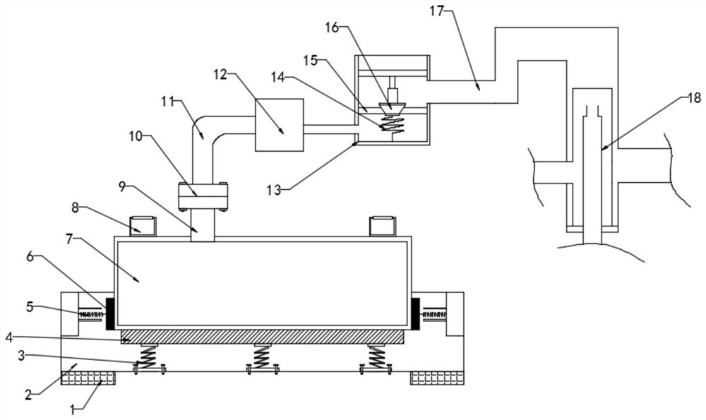
[0022] see figure 1 , in Embodiment 1 of the present invention, an air compressor waste heat recovery device, which includes: a mounting seat 2 and an air compressor body 7, seat cushions 1 are provided on the left and right sides of the lower end of the mounting seat 2, and the seat cushion 1 is raised The stability of the air compressor waste heat recovery device when it is placed; the installation seat 2 is provided with a buffer assembly, and the air compressor body 7 is placed on the buffer assembly inside the installation seat 2, and the air compressor body 7 is supported by the buffer assembly. Shock absorption during operation;

[0023] The upper end of the air compressor body 7 is connected to the main outlet pipe 9, and the upper end of the main outlet pipe 9 is connected to the suction fan 12 through the cooperation of the connection assembly 10 and the suction pipe 11, and one end of the suction fan 12 is connected to the temporary storage box 13, An air outlet co...

Embodiment 2

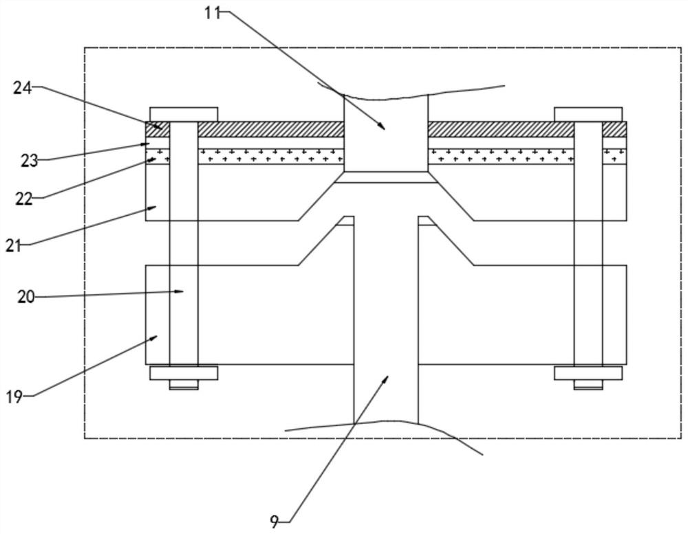
[0029] see figure 2 , further, the connection assembly 10 includes a first flange 19 and a second flange 21, and the first flange 19 and the second flange 21 are connected by bolts 20;

[0030] Specifically, a channel is provided inside the first flange 19, the lower end of the channel inside the first flange 19 is connected to the main steam outlet pipe 9, and a protrusion is provided on the upper end of the first flange 19; the second flange 21 There is a channel inside, the upper end of the channel inside the second flange 21 is connected to the suction pipe 11, and the lower end of the second flange 21 is provided with a groove; when the first flange 19 and the second flange 21 are assembled, the first method The protrusion at the upper end of the flange 19 is placed inside the groove at the lower end of the second flange 21, so that the main outlet pipe 9, the passage inside the first flange 19, the passage inside the second flange 21 and the suction pipe 11 are connecte...

Embodiment 3

[0034] Further, the air outlet assembly includes a movable plug 16, a partition 15 is arranged inside the temporary storage box 13, and the partition 15 divides the inside of the temporary storage box 13 into two cavities, the upper and lower cavities are passed through the partition The channel provided on 15 is connected, and a movable plug 16 is installed in the channel;

[0035] Specifically, the lower end of the movable plug 16 is connected to the inner wall of the bottom end of the cavity through the third compression spring 14, and the upper end of the movable plug 16 is sleeved and movably installed on the sleeve rod provided in the cavity;

[0036] When starting the suction fan 12, the suction fan 12 makes the high-temperature steam entering the temporary storage box 13 have pressure, pushes the movable plug 16 to move upwards, opens the passage on the partition plate 15, and makes the steam output; when the suction fan 12 stops During operation, the high-temperature ...


PUM


Abstract

The invention belongs to the field of air compressor auxiliary equipment, and particularly relates to a waste heat recovery device for an air compressor. The waste heat recovery device for the air compressor comprises a mounting base and an air compressor body. A buffer assembly is arranged in the mounting base, the upper end of the air compressor body communicates with a main steam outlet pipe, and the upper end of the main steam outlet pipe communicates with a suction fan through cooperation of a connecting assembly and an air suction pipe. One end of the suction fan communicates with a temporary storage box, and an air outlet assembly is installed in the temporary storage box. One end of the temporary storage box communicates with a waste heat recovery assembly through a secondary steamoutlet pipe. The waste heat recovery device for the air compressor has the following advantages that firstly, the buffer assembly is arranged to clamp and fix the air compressor body, and meanwhile the buffer damping effect is achieved; and secondly, a first flange and a second flange which are connected together through an anti-expansion gasket arranged on the connecting assembly are not prone to looseness even after thermal expansion and cold contraction occurs, the sealing performance of the first flange and the second flange which are assembled together is guaranteed through a sealing plate, leakage is not easy to happen, and heat loss is reduced.

Description

technical field [0001] The invention relates to the field of air compressor auxiliary equipment, in particular to an air compressor waste heat recovery device. Background technique [0002] Manufacturers who use air compressors generally do not recycle the waste heat generated during the working process of the air compressor, and this part of the waste heat is emptied and wasted in vain, resulting in a waste of energy. It is calculated that a 120Kw air compressor can dissipate 302MJ of heat in one hour, which is equivalent to the heat generated by burning 17.7Kg of coal. Therefore, how to recover and use these exhausted heat energy is a very meaningful work. For this reason, the patent authorization announcement number is that a kind of multifunctional air compressor waste heat recovery device is provided in the patent application document of CN207315601U. [0003] The multi-functional air compressor waste heat recovery device is conducive to improving the waste heat utili...

Claims


Application Information

Patent Timeline
Patent Type & Authority Applications(China)
IPC IPC(8): F04B39/06F04B39/12F04B39/14F04B39/00
CPCF04B39/00F04B39/0044F04B39/06F04B39/123F04B39/14
Inventor 张雄
Owner 张雄
Why Eureka
Try Eureka