
Miniaturized MEMS (Micro Electro Mechanical System) capacitive composite resonance type vector hydrophone

A vector hydrophone, capacitive technology, applied in instruments, measuring devices, electrical devices, etc., can solve problems such as lack of scalar sound pressure detection capability, inability to accurately obtain sound field information, and complex suspension structure, to ensure the acquisition of Integrity and accuracy, simplicity of construction, effect of reducing size and volume

Pending Publication Date: 2020-10-02
NO 54 INST OF CHINA ELECTRONICS SCI & TECH GRP
View PDF2 Cites 6 Cited by
  • Summary
  • Abstract
  • Description
  • Claims
  • Application Information

AI Technical Summary

Problems solved by technology

[0005] In the patent with publication number CN1776390A, "capacitive co-oscillating vector hydrophone and its technology" are disclosed. The vector hydrophone uses silicon micro-acceleration sensor as a sensitive element, but does not have scalar sound pressure detection capability; in the publication number In the patent of CN208795359U, a "two-dimensional co-vibration type vector hydrophone" is disclosed. Although this structure can realize sound pressure and vibration velocity composite information detection, there are the following problems: 1) the vibration velocity sensing element and the sound pressure Sensing elements are arranged vertically, resulting in a larger size
2) The vibration velocity sensing element and the sound pressure sensing element are not concentric, and the sound field information cannot be accurately obtained
3) The suspension structure is relatively complicated and requires eight springs to support

Method used


Image

  • Miniaturized MEMS (Micro Electro Mechanical System) capacitive composite resonance type vector hydrophone
  • Miniaturized MEMS (Micro Electro Mechanical System) capacitive composite resonance type vector hydrophone
  • Miniaturized MEMS (Micro Electro Mechanical System) capacitive composite resonance type vector hydrophone

Examples


Embodiment Construction

[0026] Below, the present invention will be further described in conjunction with the accompanying drawings and specific embodiments.

[0027] The theoretical basis of scalar signal detection is: when the piezoelectric ceramic ring acts in the sound field, it can receive the acoustic signal excitation from the water medium, force the piezoelectric material to produce forced vibration and deformation, and induce the charge, thereby converting the vibration signal It is an electrical signal output to realize scalar detection of acoustic signals.

[0028] The theoretical basis of vector signal detection is: if the geometric size of the acoustically rigid body is smaller than the wavelength, then when it vibrates freely under the action of sound waves in water, the vibration velocity amplitude V of the rigid cylinder is related to the geometry of the cylinder in the sound field. Vibration velocity amplitude V of the water particle at the center of gravity 0 The following relation...


PUM


Abstract

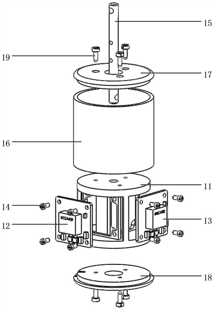
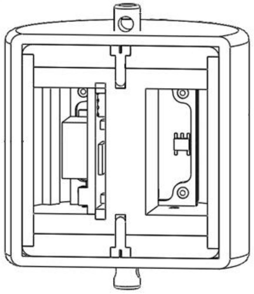
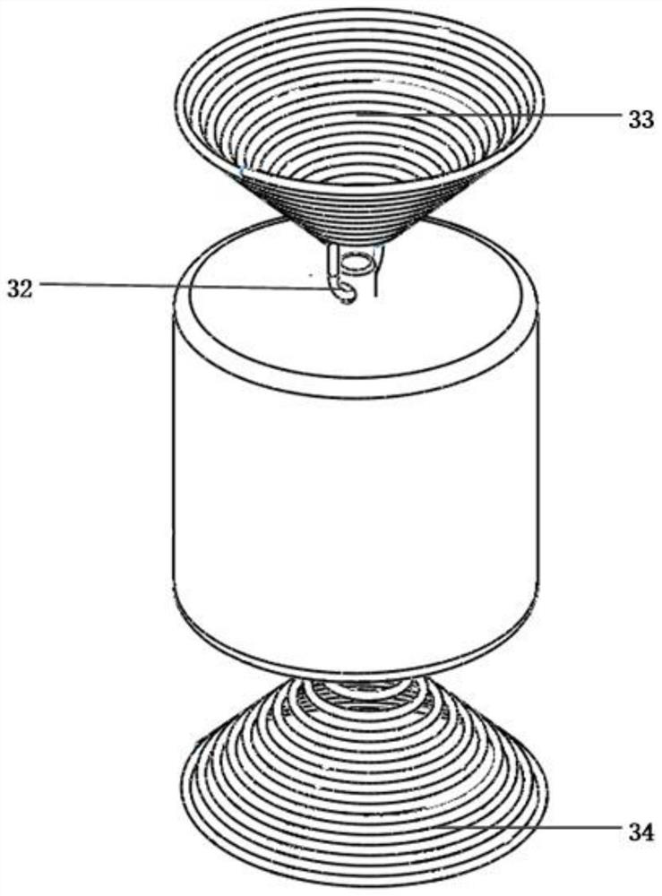
The invention discloses a miniaturized MEMS capacitive composite resonance type vector hydrophone, and belongs to the technical field of underwater acoustic signal detection. The vector hydrophone comprises an MEMS capacitive accelerometer, a fixed core, a vertical suspension rod, a piezoelectric ceramic ring, an acoustic transmission sealing shell, and a conical spiral spring. The MEMS capacitiveacceleration sensor is orthogonally arranged in the fixed core; the vertical suspension rod penetrates through the whole fixed core; the piezoelectric ceramic ring sleeves the outside of the fixed core; and the acoustic transmission sealing shell covers the piezoelectric ceramic ring through a potting process. The conical spiral spring is connected with the vertical suspension rod, and the hydrophone is hung on a fixing support for use. The size of the hydrophone is reduced, sound pressure signals and vibration velocity signals at the same underwater position can be detected, the accuracy ofsignal detection is improved, and the hydrophone is simple in structure, good in consistency and high in reliability.

Description

technical field [0001] The invention relates to the technical field of underwater acoustic signal detection, in particular to a miniaturized MEMS capacitive composite co-vibration vector hydrophone. Background technique [0002] Traditional scalar hydrophones, also known as sound pressure hydrophones, are generally made of piezoelectric ceramics and other materials, and have various shapes and sizes. They are mostly used as standard hydrophones, but they can only measure scalar parameters in the sound field. [0003] The core sensing element inside the traditional co-vibration vector hydrophone is the vibration sensor. Most of the vibration sensors used in hydrophone processing at home and abroad are acceleration or speed sensors based on the piezoelectric principle. This traditional piezoelectric vector hydrophone is large in size and heavy in weight, and requires complex processing circuits at the back end, and is limited by traditional processing techniques, resulting in...

Claims


Application Information

Patent Timeline
IPC IPC(8): G01H11/06
CPCG01H11/06
Inventor 张松王大宇董自强张晓桐苗峻
Owner NO 54 INST OF CHINA ELECTRONICS SCI & TECH GRP
Learn More