Sensor assembly shell, leadless thermopile sensor and manufacturing method

A thermopile sensor, sensor technology, applied in instruments, measuring devices, scientific instruments, etc., can solve the problems of hindering epidemic prevention work, poor shock resistance, inaccurate body temperature parameters, etc., to save binding lead space and lead connection. Process, the effect of reducing the overall size

Pending Publication Date: 2020-10-02
HENAN HANWEI ELECTRONICS
View PDF10 Cites 2 Cited by
  • Summary
  • Abstract
  • Description
  • Claims
  • Application Information

AI Technical Summary

Problems solved by technology

[0004] However, sensors with wire-bonded package structures are generally large in size, which is difficult to meet the application of thermopile sensors in small-sized electronic products such as earphones, mobile phones, and wearable devices.
[0005] Under the new crown epidemic, the detection accuracy of temperature measurement products and temperature measurement sensors is particularly important, but temperature measurement products made of thermopile sensors with wire-bonded packaging structures have technical problems of low detection accuracy and poor shock resistance; low detection accuracy It may lead to inaccurate body temperature parameters of some personnel, and the poor shock resistance of thermopile sensors may affect the service life of temperature measurement products, thereby hindering the progress of epidemic prevention work

Method used


Image

  • Sensor assembly shell, leadless thermopile sensor and manufacturing method
  • Sensor assembly shell, leadless thermopile sensor and manufacturing method
  • Sensor assembly shell, leadless thermopile sensor and manufacturing method

Examples


Embodiment 1

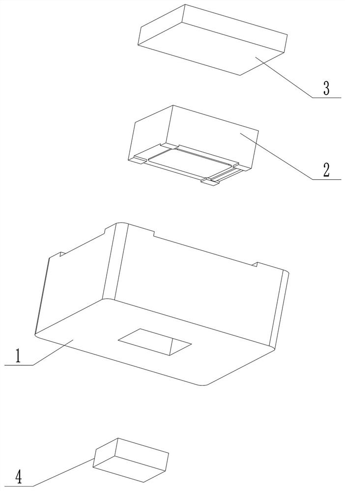
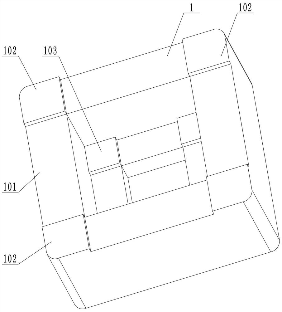
[0044] attached Figures 2 to 4 A sensor assembly housing is shown, the sensor assembly housing 1 is provided with a detection chamber for accommodating at least one thermopile sensitive chip, and the top of the detection chamber is provided with an internal conductive wire for electrically connecting the thermopile sensitive chip. Bump 103, the outer wall of the sensor assembly housing 1 is provided with an external pin 102 for outputting a detection signal; the external pin 102 is connected to the internal conductive bump 103 to detect the thermopile sensitive chip 2 The signal is output via the external pin. The inner conductive bump is an inner pad.

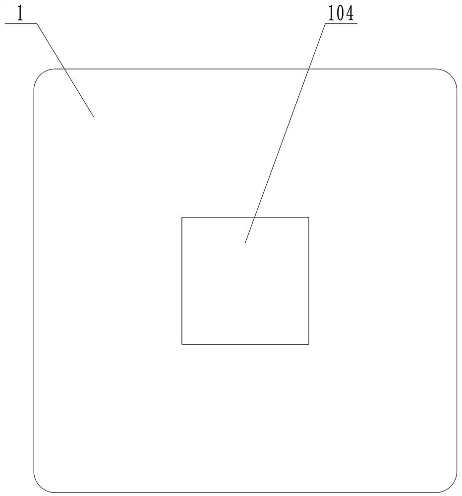
[0045] In this embodiment, the optical filter 4 is mounted in the window 104 opened on the top of the detection chamber; the bottom plate 3 is covered above the installation port of the bottom 101 of the detection chamber, and the housing is assembled with the sensor 1 is sealed and connected, and the bottom plate 3, the op...

Embodiment 2

[0053] This embodiment provides a specific implementation of a single-channel leadless thermopile sensor, as attached figure 1 And attached Figure 6 shown.

[0054] The leadless thermopile sensor comprises the above-mentioned sensor assembly housing, thermopile sensitive chip 2 and optical filter 4; The surface is set corresponding to the filter 4; the detection surface of the thermopile sensitive chip 2 is provided with electrode pads 201 on the same side, and the electrode pads 201 of at least one thermopile sensitive chip are electrically conductive with the inside of the top of the detection chamber. The bumps 103 are contacted and connected to realize the electrical connection between the thermopile sensitive chip 2 and the sensor assembly housing.

[0055] This embodiment provides a specific implementation of a sensor assembly housing, the sensor assembly housing includes a sensor assembly housing 1 and a bottom plate 3, the sensor assembly housing 1 is provided with ...

Embodiment 3

[0063] On the basis of the above-mentioned leadless thermopile sensor, the present invention also provides a manufacturing method of the leadless thermopile sensor.

[0064] The manufacturing method of the leadless thermopile sensor includes the following steps: attaching the optical filter 4 in the window 104 on the top of the detection chamber through epoxy resin glue, so as to ensure the airtight connection between the optical filter and the sensor assembly housing , to avoid light leakage; turn the above-mentioned sensor assembly housing 1 upside down, apply conductive glue on the internal conductive bump 103 on the top of the detection chamber through a glue dispenser, and place the thermopile sensitive chip 2 into the sensor assembly housing 1 In the detection chamber, wherein, the detection surface of the thermopile sensitive chip 2 is set corresponding to the optical filter 4, so that the electrode pad 201 of the thermopile sensitive chip is in contact with the internal...


PUM


Abstract

The invention provides a sensor assembly shell, a leadless thermopile sensor and a manufacturing method. The leadless thermopile sensor comprises the sensor assembly shell and a thermopile sensitive chip; the detection surface of the thermopile sensitive chip is correspondingly arranged below the top of the inner wall of the detection cavity of the sensor assembly shell; and an electrode bonding pad of at least one thermopile sensitive chip is in contact connection with an internal conductive convex block at the top of the detection cavity, so that the thermopile sensitive chip is electricallyconnected with the sensor assembly shell. According to the invention, the assembly process of the lead is reduced, the operation difficulty of the assembly process is greatly simplified, the assemblyefficiency is improved, and the technical problem of complex process of the existing thermopile sensor is solved; meanwhile, in terms of structural design, a lead binding space is omitted, the overall size of the leadless thermopile sensor is greatly reduced, and the problem that application of a thermopile sensor in the prior art is limited in electronic products due to the fact that the size ofthe thermopile sensor is too large is effectively solved.

Description

technical field [0001] The invention relates to the technical field of thermopile sensors, in particular to a sensor assembly shell, a leadless thermopile sensor and a manufacturing method. Background technique [0002] A thermopile sensor consists of multiple thermal elements combined into a thermoelectric array or thermopile. Thermopile sensors determine the physical temperature or gas concentration by monitoring the infrared radiation of an object. When the thermosensitive element receives the infrared radiation radiated by the object, there will be a heat difference between the hot end and the cold end of the thermosensitive element. Based on the Seebeck principle, the voltage output by the thermopile sensor will change. Entering the era of MEMS sensors, advanced semiconductor technology can process hundreds of pairs of thermocouples in a very small space to build infrared thermopile sensors. With MEMS technology, the size of infrared thermopile sensors has become very...

Claims


Application Information

Patent Timeline
Patent Type & Authority Applications(China)
IPC IPC(8): G01J5/12G01J5/04
CPCG01J5/12G01J5/04G01J2005/123
Inventor 高胜国杨志博郭海周王利利田勇古瑞琴
Owner HENAN HANWEI ELECTRONICS
Why Eureka
Try Eureka