
Induced discharge current testing method and device for power distribution live-line work robot

A technology of discharge current and live work, applied in the field of induction discharge current testing of power distribution live work robots, can solve problems such as failure to work normally, induction discharge frequency bandwidth, measurement result error, etc., and achieve the effect of meeting operational requirements

Active Publication Date: 2020-10-02
天津滨电电力工程有限公司 +3
View PDF7 Cites 0 Cited by
  • Summary
  • Abstract
  • Description
  • Claims
  • Application Information

AI Technical Summary

Problems solved by technology

Due to the wide frequency range and high amplitude of inductive discharge, strong interference will be generated in the surrounding environment, and the device for measuring current has no electromagnetic protection, so the error of the measurement result is very large, and it even cannot work normally.
[0004] At present, there is no test device for 0-GHz broadband and strong current. Therefore, it is urgent to combine the special electromagnetic environment of the operation of the power distribution robot, and equip the induction discharge current test device that is resistant to strong electromagnetic interference, and propose a method for testing the induction discharge current of the power distribution robot.

Method used


Image

  • Induced discharge current testing method and device for power distribution live-line work robot
  • Induced discharge current testing method and device for power distribution live-line work robot
  • Induced discharge current testing method and device for power distribution live-line work robot

Examples


Embodiment Construction

[0064] It should be noted that, in the case of no conflict, the embodiments of the present invention and the features in the embodiments can be combined with each other.

[0065] In the description of the present invention, it should be understood that the orientations or positional relationships indicated by the terms "top", "bottom", "inner", "outer" and the like are based on the orientations or positional relationships shown in the accompanying drawings, and are only In order to facilitate the description of the invention and simplify the description, it does not indicate or imply that the device or element referred to must have a specific orientation, be constructed and operated in a specific orientation, and thus should not be construed as limiting the invention. In addition, the terms "first", "second", etc. are used for descriptive purposes only, and should not be interpreted as indicating or implying relative importance or implicitly specifying the quantity of the indic...


PUM


Abstract

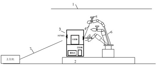
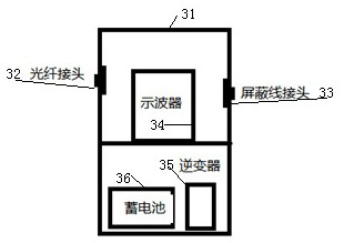
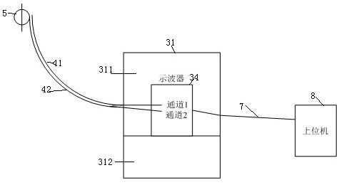
The invention provides an induced discharge current testing method and device for a power distribution live-line work robot. The induced discharge current testing device comprises current measuring equipment, a discharge electrode and a current sensor. The current measuring equipment comprises a shielding box, an oscilloscope and a device for providing power for the operation of the oscilloscope are arranged in the shielding box, the side wall of the shielding box is provided with joints which are in butt joint with the outside, namely an optical fiber joint and a shielded wire joint, and theoscilloscope is connected with an upper computer through the optical fiber joint; and after the discharge electrode is connected with the current sensor through a discharge current measuring cable, the discharge current measuring cable penetrates through the shielded wire joint to be connected with the input end of the oscilloscope. The current measuring equipment, the discharge electrode and thecurrent sensor are reasonably matched and connected, so that the robot induced discharge current in the space radiation field can be tested in time.

Description

technical field [0001] The invention belongs to the field of electromagnetic compatibility of high-voltage power transmission and substation engineering, and in particular relates to a method and device for testing the induced discharge current of a power distribution live working robot. Background technique [0002] It is an inevitable direction of technological development that live working robots replace workers in live working in distribution networks. In order to meet the requirements of live work on distribution lines, a high-voltage live work robot that meets the requirements of the on-site working environment to the greatest extent is currently being developed. The robot is exposed to harsh electromagnetic environments, and EMC testing and evaluation are urgently needed. [0003] When the power distribution robot is working with electricity, various ports are exposed to the complex electromagnetic generated by the high-voltage line, and the robot may malfunction or r...

Claims


Application Information

Patent Timeline
IPC IPC(8): G01R19/00G01R19/04G01R1/18G01R31/00
CPCG01R1/18G01R19/0092G01R19/04G01R31/001
Inventor 胡益菲张黎明陈竟成于建成项添春王谦路菲刘倞王立国余光凯刘庭刘凯肖宾彭勇郑秋玮
Owner 天津滨电电力工程有限公司
Learn More