
Novel laser cutting machine

A laser cutting machine, a new technology, applied in the direction of laser welding equipment, welding/cutting auxiliary equipment, auxiliary devices, etc., can solve the problems of low cutting accuracy, large space occupation, heavy weight, etc., to save vertical space and facilitate installation The effect of disassembly

Inactive Publication Date: 2020-10-09
沧州领创激光科技有限公司
View PDF7 Cites 0 Cited by
  • Summary
  • Abstract
  • Description
  • Claims
  • Application Information

AI Technical Summary

Problems solved by technology

[0002] As we all know, a laser cutting machine is a kind of energy released when the laser beam is irradiated on the surface of the workpiece to melt and evaporate the workpiece to achieve the purpose of cutting and engraving. It has high precision, fast cutting, not limited to cutting patterns, and automatic typesetting. Material saving, smooth incision, low processing cost and other characteristics will gradually improve or replace traditional cutting process equipment, which has been widely used in the field of cutting equipment; the existing laser cutting machine is heavy and takes up more space. Large, and the dust removal effect is poor, and the cutting accuracy is low

Method used


Image

  • Novel laser cutting machine
  • Novel laser cutting machine
  • Novel laser cutting machine

Examples


Embodiment Construction

[0019] The specific implementation manners of the present invention will be further described in detail below in conjunction with the accompanying drawings and embodiments. The following examples are used to illustrate the present invention, but are not intended to limit the scope of the present invention.

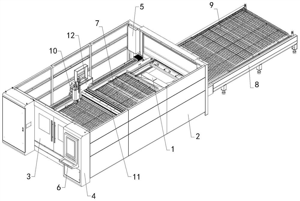
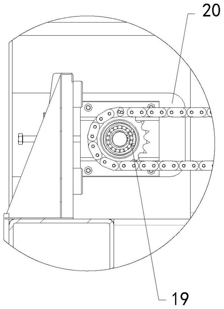
[0020] Such as Figure 1 to Figure 7 As shown, a new type of laser cutting machine of the present invention includes a base 1, a cover 2 is arranged on the base 1, a switch door 3 is arranged at the front end of the cover 2, an operation cabinet 4 is arranged at the front end of the cover 2, and inside the cover 2 The left half area of ​​the rear side wall is provided with a gas circuit cabinet 5, a display screen 6 is provided on the operation cabinet 4, an upper cutting workbench 7 is provided on the top of the base 1, an auxiliary workbench 8 is arranged on the back side of the base 1, and an auxiliary workbench 8 is arranged on the top of the base 1 A lower cutting ta...


PUM


Abstract

The invention relates to the technical field of accessory devices of cutting equipment, in particular to a novel laser cutting machine. According to the novel laser cutting machine, the overall weightof the device can be effectively reduced, the occupied space is reduced, the dust removal effect is good, and the cutting accuracy is high. The novel laser cutting machine comprises a base, wherein acover shell is arranged on the base, a switching door is arranged at the front end of the cover shell, an operating cabinet is arranged at the front end of the cover shell, a gas circuit cabinet is arranged in the left half area of the rear side wall in the cover shell, a display screen is arranged on the operating cabinet, a cutting worktable is arranged at the top end of the base, an auxiliaryworktable is arranged on the rear side of the base, a lower cutting worktable is arranged on the auxiliary worktable, a cross beam is welded to a first base, a Z-axis is arranged on the cross beam, and a laser cutting mechanism is arranged on the Z-axis; and the laser cutting mechanism further comprises a second base and a guide rail, a bumping block and a sliding block are correspondingly arranged in the front half area and the rear half area of the bottom end of the second base, and a servo module assembly is arranged on the Z-axis.

Description

technical field [0001] The invention relates to the technical field of cutting equipment attachments, in particular to a new type of laser cutting machine. Background technique [0002] As we all know, a laser cutting machine is a kind of energy released when the laser beam is irradiated on the surface of the workpiece to melt and evaporate the workpiece to achieve the purpose of cutting and engraving. It has high precision, fast cutting, not limited to cutting patterns, and automatic typesetting. Material saving, smooth incision, low processing cost and other characteristics will gradually improve or replace traditional cutting process equipment, which has been widely used in the field of cutting equipment; the existing laser cutting machine is heavy and takes up more space Large, and the dust removal effect is poor, and the cutting accuracy is low. Contents of the invention [0003] In order to solve the above technical problems, the present invention provides a new typ...

Claims


Application Information

Patent Timeline
IPC IPC(8): B23K26/38B23K26/70B23K37/04B08B5/02B08B5/04B08B13/00
CPCB08B5/02B08B5/04B08B13/00B23K26/38B23K37/0461B23K26/702
Inventor 白素涛郭庆硕
Owner 沧州领创激光科技有限公司
Learn More