Thermal spinning film deaerator

A deaerator, membrane technology, applied in the field of thermal spin film deaerator, can solve the problems of energy waste, exhaust noise, etc., and achieve the effect of expanding the contact surface area

Active Publication Date: 2021-09-17
连云港久盛电力辅机有限公司
View PDF8 Cites 0 Cited by
  • Summary
  • Abstract
  • Description
  • Claims
  • Application Information

AI Technical Summary

Problems solved by technology

[0005] The solution provided by the prior art can better remove the oxygen in the water body, but since the non-condensable gas is directly discharged from the exhaust pipe to the atmosphere during the oxygen removal process, the exhaust noise is large during the process of removing the non-condensable gas. At the same time, part of the steam is also discharged together, resulting in a waste of part of the energy

Method used


Image

  • Thermal spinning film deaerator
  • Thermal spinning film deaerator
  • Thermal spinning film deaerator

Examples


Embodiment 1

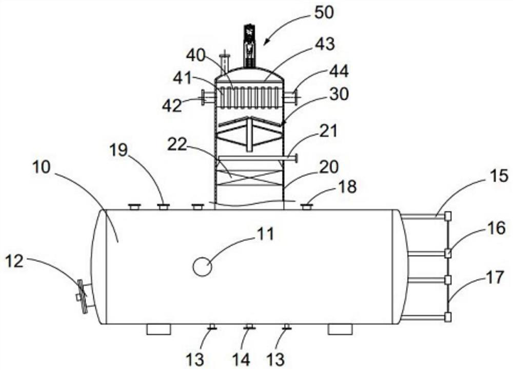
[0037] See attached Figure 1-10 As shown, the thermal rotary film deaerator includes:

[0038] The first oxygen removal housing 10, the first oxygen removal housing 10 is placed horizontally;

[0039] The second deaeration housing 20, the second deaeration housing 20 is placed vertically and is arranged on the top of the first deaeration housing 10, the first deaeration housing 10 and the second deaeration housing 20 are hollowly arranged inside and connected;

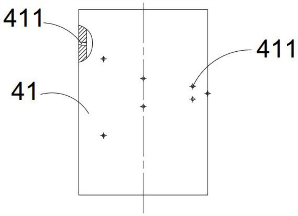
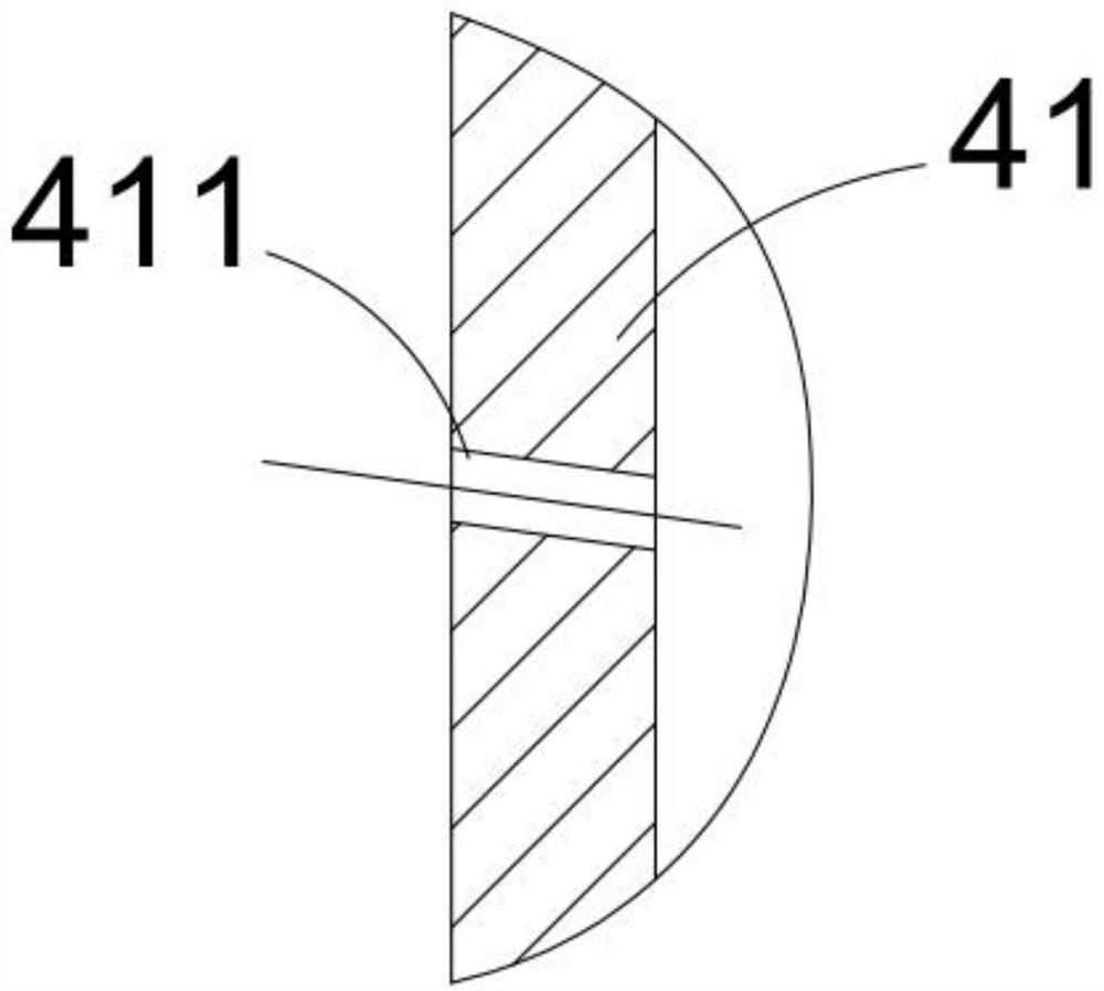
[0040] The upper part of the second deaeration housing 20 is provided with a water chamber 40, and the second deaeration housing 20 on both sides of the water chamber 40 is respectively connected with the first water supply inlet 42 and the second water supply inlet 44. The provided nozzle 41, the upper and lower ports of the nozzle 41 are all arranged on the outside of the water chamber 40, the surface of the nozzle 41 is spirally arranged with water inlet holes 411, and the upper end of the second deaeration housi...

Embodiment 2

[0051] The further optimization scheme of present embodiment on the basis of embodiment 1 is: see appendix Figure 11-13 As shown, the first deaeration housing 10 is provided with a limit box 70, the upper end of the limit box 70 is connected to the inner upper wall of the first deaeration housing 10, and the lower end of the limit box 70 is connected to the first deaeration housing. 10, the inner lower wall is connected, the limit box 70 lower side wall is provided with a water inlet through hole 71, the limit box 70 is provided with a buoyancy member 72, the limit box 70 upper side wall is connected with a communication base 74, communicates A limit cavity 79 is provided in the base part 74, and a fourth air delivery hole 78 that passes through the base part 74 is also provided on the communication base part 74, so that the gas is passed into the limit box 70, and the communication base part 74 passes through the pipe body. Connect with the tee pipe 76, the other mouth of th...

Embodiment 3

[0053] The further optimization plan of this embodiment on the basis of Embodiment 1 is as follows: a water retaining plate 43 is provided above the water chamber 40, through holes or mesh holes are arranged on the surface of the water retaining plate 43, and a thermometer is provided outside the first deaeration housing 10 11. The detection probe of the thermometer 11 is set in the first deaeration housing 10 .


PUM


Abstract

The invention discloses a thermal spinning membrane deaerator, which belongs to the technical field of boiler feed water deaeration. The upper part of the housing, the first deaeration housing and the second deaeration housing are hollow and communicated with each other, the upper part of the second deaeration housing is provided with a water chamber, and the second deaeration housing on both sides of the water chamber is connected to the water inlet , a vertical nozzle pipe is arranged in the water chamber, the upper and lower ports of the nozzle pipe are arranged outside the water chamber, the water inlet hole is spirally arranged on the surface of the nozzle pipe, the upper end of the second deaeration shell on the upper part of the water chamber is connected to the exhaust assembly, and the water chamber A water distribution component is installed in the second deaeration shell at the lower part, a packing layer is set under the water distribution component, and a third steam input pipe is set between the water distribution component and the packing layer; Effectively recycle water and reduce steam discharge, solve the problem of exhaust with water to reduce water resource loss, stable operation, no vibration and noise.

Description

technical field [0001] The invention belongs to the technical field of boiler feed water deaeration, and in particular relates to a thermal spin film deaerator. Background technique [0002] With the development of high-parameter and large-capacity generator sets, the system is becoming more and more complex, and the increase in the capacity of a single unit makes the requirements for the economy, safety and reliability of the entire unit operation higher, and the requirements for water supply quality are becoming more and more stringent. The presence of dissolved oxygen in water is an important cause of corrosion. In order to make the unit run safely and stably, and to prevent the corrosion of boiler and steam turbine equipment, it is necessary to reduce the oxygen content of the feed water. In addition, the dissolved oxygen in the condensed water also affects the operation safety of the water supply system and the entire thermal system. When the condensed water with high ...

Claims


Application Information

Patent Timeline
Patent Type & Authority Patents(China)
IPC IPC(8): C02F1/20F22D1/50
CPCC02F1/20F22D1/50
Inventor 谢其志
Owner 连云港久盛电力辅机有限公司
Why Eureka
Try Eureka