
A vibration device for a resonance crusher

A vibrating device and crusher technology, applied in roads, constructions, road repairs, etc., can solve problems such as large oil cylinder force, uneven force force on gears, inconsistent wear, etc., to achieve strong road surface adaptability, stable vibration frequency, and avoid Tilt shake effect

Active Publication Date: 2022-04-29
武汉海德力液压技术有限公司
View PDF5 Cites 0 Cited by
  • Summary
  • Abstract
  • Description
  • Claims
  • Application Information

AI Technical Summary

Problems solved by technology

The vibration device of this patent rotates around the hinge shaft at the front end as a whole. The angle of the rotating arm causes the angle of the hammer head to change. The upper and lower ranges are not large due to the guidance and angle constraints. The position adjustment space of the vibration box is small, and the force on the oil cylinder is large, which is easy to cause equipment damage.
[0004] 2. Large lateral size: Resonance crushers generally adopt the structure of vibration box plus shock absorber. Most of the vibration boxes are arranged horizontally. When the power of the vibration system needs to be increased, the number of vibration shafts needs to be increased. The entire vibration box The transverse dimension of the horizontal dimension will increase, and it is difficult to enter the narrow area for construction; when the transverse dimension increases, the distance between the shock absorbers at both ends is relatively large, and the shock absorbers at both ends are affected by frictional resistance and positive pressure above the vibrating device during the working process. The situation of uneven force is obvious. Usually, the shock absorber at the rear end is subjected to greater force, resulting in easy damage
At the same time, the vibration box of this type of vibration device is prone to irregular jumps in the front and rear and left and right, resulting in poor vibration stability and relatively poor resonance effect.
[0005] 3. Poor stability: The vibration axes in the vibration box of some resonance crushers are arranged longitudinally, and the arrangement includes 3X type (patent CN2015103648186) and 4Z type (patent CN2018110260164). The size of the wheel is calculated accurately. If there is a deviation in the calculation or processing, the vibration box will shake seriously in the horizontal direction. Due to the inevitability of the error, the 3X vibration structure has poor working stability and the service life of the equipment is short. Insufficient; although the component force of the 4Z structure in the horizontal direction has two opposite forces of the same size, there is a deflection moment around the center of the vibrating box, which makes the vibrating box vibrate significantly in the left and right directions during work; at the same time, no matter whether the 3X or 4Z structure The middle part of the gear has two meshing points, and the upper and lower gears have one meshing point, which makes the meshing force of the gears different, resulting in uneven force and inconsistent wear of the gears, and a short service life of the gears.

Method used


Image

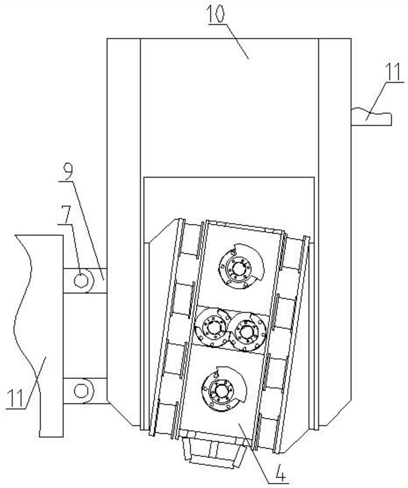
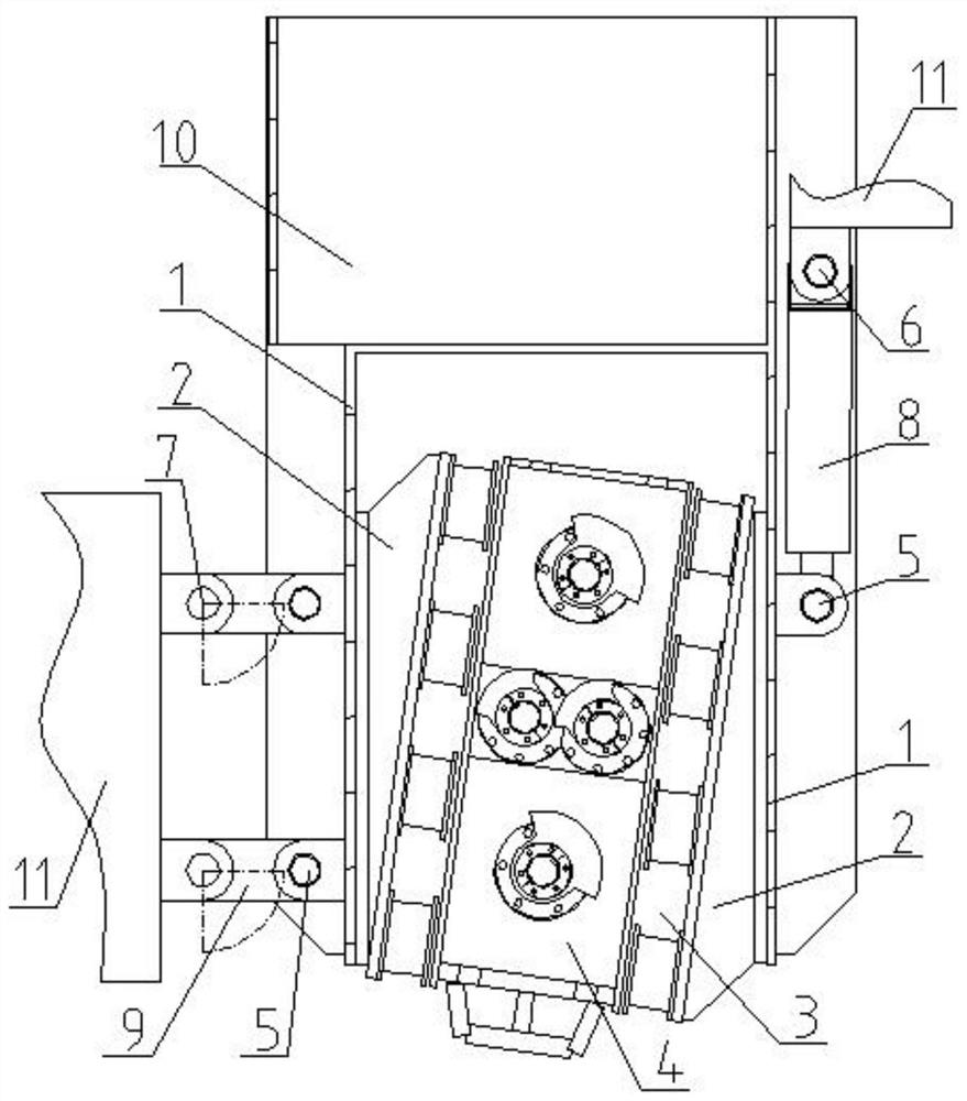
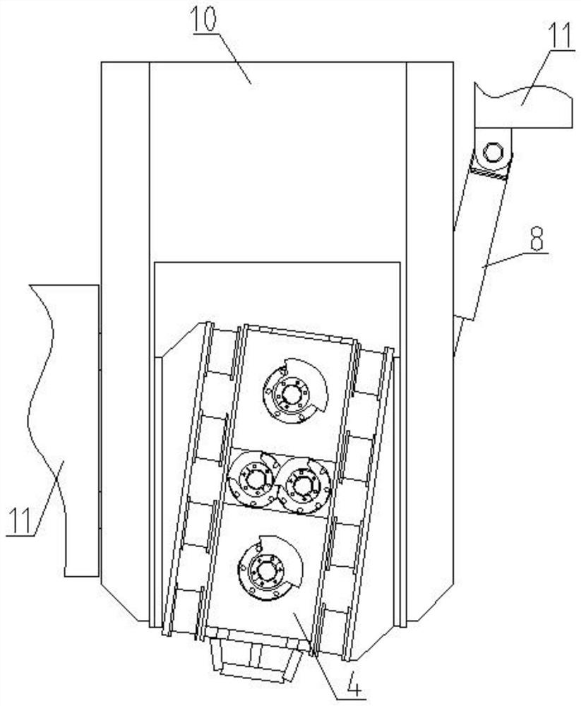
  • A vibration device for a resonance crusher
  • A vibration device for a resonance crusher
  • A vibration device for a resonance crusher

Examples


Embodiment 1

[0050] The number of eccentric shafts is 4, and the 4 eccentric shafts are arranged in a diamond shape, such as Figure 5 shown. The eccentric moment of the upper and lower eccentric shafts is M1, the centrifugal force generated by the eccentric shaft is F1, the eccentric moment of the middle eccentric shaft is M2, and the centrifugal force generated by the eccentric shaft is F2, M1 and M2 are the same in size and opposite in direction, F1 and F2 are the same size same direction opposite.

[0051] Different from the traditional eccentric shaft vibration mode, the direction of the exciting force F is through the line connecting the upper and lower eccentric shaft centers, and the two exciting forces are symmetrically distributed relative to the axis, while ensuring that the gears are evenly stressed.

[0052] To realize the vibration with greater excitation force (or greater vibration energy), the eccentric weight of the eccentric shaft or eccentric weight can be increased.

...

Embodiment 2

[0055] The number of eccentric shafts is 6, such as Figure 6 As shown, one at the upper end and one at the lower end, two eccentric shafts are arranged in each row in the middle two rows, the component forces in the horizontal direction of the vibration unit cancel each other out, and the component forces in the vertical direction superimpose each other to form an exciting force F, forming a regular sine The wave vibrates.

Embodiment 3

[0057] The number of eccentric shafts is 8, such as Figure 7 As shown, there is one at the upper end and one at the lower end, and two eccentric shafts are arranged in each of the three rows in the middle. The component forces in the horizontal direction of the vibration unit cancel each other out, and the component forces in the vertical direction superimpose each other to form an exciting force F, forming a regular sine The wave vibrates.


PUM


Abstract

The invention discloses a vibrating device for a resonance crusher, which comprises a mounting bracket and a vibrating unit; the mounting bracket includes two vertically arranged bracket poles, and hinge shaft earrings are arranged on the outside of the bracket poles; one side of the crushing locomotive There is a front hinge seat on the body, and an oil cylinder is connected to the front hinge seat, and the free end of the oil cylinder is connected to the hinge earring on the support pole; on the other side, there are two or more rear hinge seats horizontally on the crusher body. , the central connection line of the rear hinge seat is parallel to the support vertical rod, the rear hinge seat is connected to the hinge earring on the support vertical rod through the connecting rod, the central connection line of the rear hinge seat, the connecting rod and the adjacent support vertical rod form Parallelogram structure, by adjusting the length of the oil cylinder to change the shape of the parallelogram structure, thereby adjusting the height of the vibration unit from the ground, the position of the vibration unit can be adjusted in a large space, the angle of the hammer head remains unchanged during the up and down movement, the connecting rod bears the main reaction force, and the oil cylinder The force is relatively small, prolonging the service life of the entire device.

Description

technical field [0001] The invention relates to the technical field of road engineering machinery, in particular to a vibration device for a resonance crusher. Background technique [0002] Resonance crushing technology is currently the most advantageous construction solution for "white to black" cement pavement. The key construction equipment required is a resonance crusher. A resonance crusher is a road crushing machine that uses resonance technology to make the vibration The vibration frequency of the hammer head is close to the natural frequency of the cement pavement, which excites resonance, thereby crushing the cement pavement relatively easily, and has the advantages of strong power and reliable operation. The vibrating device of the existing resonance crusher mainly has the following problems: [0003] 1. The equipment is easily damaged: Patent CN2015107156547 discloses a vibration device for a resonance crusher, including a front hinge seat and a rear hinge seat r...

Claims


Application Information

Patent Timeline
Patent Type & Authority Patents(China)
IPC IPC(8): E01C23/12
CPCE01C23/124
Inventor 谢成君
Owner 武汉海德力液压技术有限公司
Learn More