High-speed electromagnetic pulse gas valve device

An electromagnetic pulse and air valve technology, which is applied in the direction of valve device, valve operation/release device, valve lift, etc., can solve the problems of large mass of moving iron core, slow response time of moving iron core movement, and slow action of electromagnetic valve, etc.

Pending Publication Date: 2020-10-09
UNIV OF SCI & TECH OF CHINA
View PDF0 Cites 3 Cited by
  • Summary
  • Abstract
  • Description
  • Claims
  • Application Information

AI Technical Summary

Problems solved by technology

If a certain amount of gas needs to be injected in a shorter time (such as on the order of milliseconds), or the gas needs to be distributed in a local area of ​​the vacuum chamber before the experimental operation, these traditional electromagnetic valves can no longer meet the demand
[0003] The reasons for the slow action of traditional solenoid valves can be summarized as follows: 1) The mass of the moving iron core of the traditional direct-acting solenoid valve is relatively large, resulting in a slow movement response time of the moving iron core; 2) Due to the winding of the external coil The wire diameters of the static iron core and the moving iron core as a piston are usually several centimeters along the direction of magnetic field diffusion, resulting in the time required for the magnetic field generated by the external coil to completely diffuse from the static iron core to the moving iron core to reach hundreds of microseconds. When the power supply is stopped, the response of the moving iron core will also be delayed by hundreds of microseconds

Method used


Image

  • High-speed electromagnetic pulse gas valve device
  • High-speed electromagnetic pulse gas valve device
  • High-speed electromagnetic pulse gas valve device

Examples


Embodiment Construction

[0020] The present invention will be further described below in conjunction with the accompanying drawings and specific embodiments.

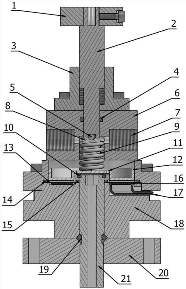
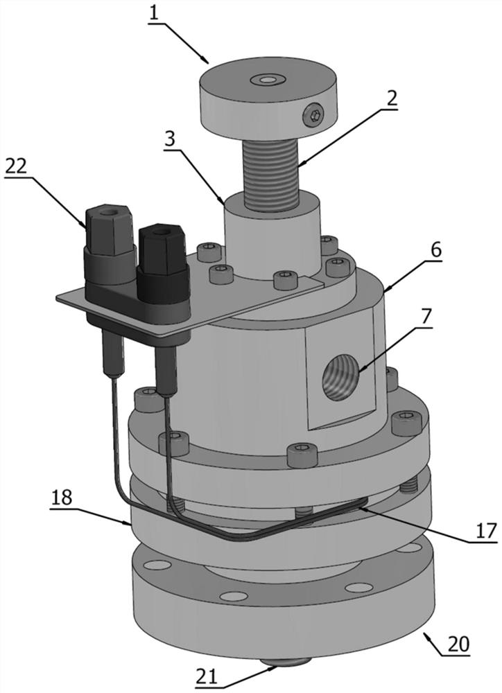
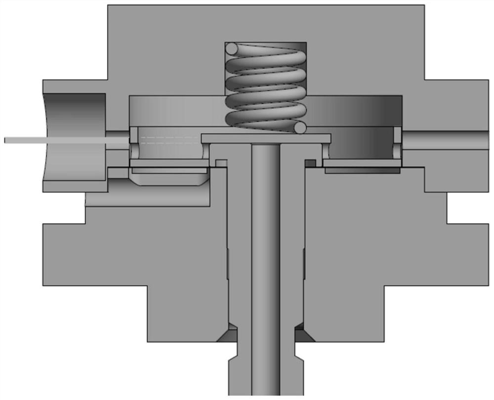
[0021] A high-speed electromagnetic pulse gas valve device of the present invention has a cavity between the valve body 18 and the gas chamber casing 6 as the gas chamber, and the air inlet 7 is used to feed the working gas into the cavity, and there is a movable valve in the cavity. Disc-shaped piston 12, the material of piston 12 is aluminum to reduce its weight. Under the action of the spring 9 , the piston 12 presses on the second O-ring 10 at the top of the lower valve stem 21 , thereby disconnecting the air path between the air chamber and the lower valve stem 21 . The degree of tightness of the spring 9 is determined by the up and down position of the spring holder 8. By rotating the handle 1, the upper valve stem 2 is driven to be screwed in and out along the threaded channel of the upper casing 3, so that the upper and lower positions...


PUM


Abstract

The invention discloses a high-speed electromagnetic pulse gas valve device. A cavity is formed between a valve body (18) and a gas chamber shell (6) to serve a a gas chamber, a gas inlet (7) is usedfor introducing working gas into the cavity, and the diffusion time of a magnetic field generated by a disc-shaped coil (16) and passing through a stainless steel sheet (13) is less than 1 microsecond. The gas inlet (7) is designed in the upper portion of the back surface of a piston (12), and the gas flows through a piston hole (11) in the piston (12), so that the pressure difference of the two sides of the piston (12) and the elastic force of a spring (9) act together to serve as a restoring force for the piston (12) to be closed downwards, thereby reducing the motion time of the closing process. By adjusting the magnitude of pulse current of the disc-shaped coil (16), the pop-up height of the piston (12) can be adjusted so as to change the movement time of opening and closing of the piston (12) and the gas intake amount. The disc-shaped coil (16) is isolated out of the gas chamber through the stainless steel sheet (13). Tests prove that a gas valve can be used for pulse gas intake of flammable and explosive gases such as hydrogen, and the bearable working pressure of the gas can be more than 0.3 Mpa.

Description

technical field [0001] The invention relates to the technical field of electromagnetic gas valves, in particular to a high-speed electromagnetic pulse gas valve device. Background technique [0002] The pulse width of traditional electromagnetic gas valves is usually more than tens of milliseconds. When the valve is closed, the injected gas has already diffused evenly in the vacuum chamber. If a certain amount of gas needs to be injected in a shorter time (such as on the order of milliseconds), or the gas needs to be distributed in a local area of ​​the vacuum chamber before the experimental operation, these traditional electromagnetic valves can no longer meet the demand. [0003] The reasons for the slow action of traditional solenoid valves can be summarized as follows: 1) The mass of the moving iron core of the traditional direct-acting solenoid valve is relatively large, resulting in a slow movement response time of the moving iron core; 2) Due to the winding of the ext...

Claims


Application Information

Patent Timeline
Patent Type & Authority Applications(China)
IPC IPC(8): F16K31/06F16K1/36F16K27/02F16K1/32F16K41/02F16K1/46
CPCF16K1/32F16K1/36F16K1/46F16K27/029F16K31/0655F16K31/0675F16K41/02
Inventor 陈晨张森兰涛庄革刘万东
Owner UNIV OF SCI & TECH OF CHINA
Why Eureka
Try Eureka