Regenerative thermal oxidation device and process for processing electroplating sludge sintering waste gas

A technology of thermal oxidation and electroplating sludge, which is applied in heat storage equipment, incinerators, combustion methods, etc., can solve problems such as low heat recovery efficiency, large fluctuations in calorific value of combustible components, and difficult cleaning of bed blockages. Low, ensure long-term safe operation, increase the effect of process unit life

Pending Publication Date: 2020-10-09
WUHAN KAIDI ELECTRIC POWER ENVIRONMENTAL
View PDF6 Cites 3 Cited by
  • Summary
  • Abstract
  • Description
  • Claims
  • Application Information

AI Technical Summary

Problems solved by technology

[0011] The technical problem to be solved by the present invention is that the heat value of the combustible components of electroplating sludge sintering waste gas fluctuates greatly in the above-mentioned prior art, the proportion of components with low spontaneous ignition point is large, and the components containing organic silicon components cause the RTO heat storage body to heat up. In order to solve the problems of low recovery efficiency and bed blockage that is difficult to clean up, a regenerative thermal oxidation device and process for treating electroplating sludge sintering waste gas can be provided, which can effectively improve the heat recovery efficiency of the regenerator, and can meet the needs of RTO devices in electroplating sludge. Long-term safe and stable operation under various working conditions where the calorific value of the components of the sintering waste gas fluctuates, and at the same time avoids the problem that the organosilicon burns inside the regenerator and causes the internal clogging of the regenerator to be difficult to clean

Method used


Image

  • Regenerative thermal oxidation device and process for processing electroplating sludge sintering waste gas

Examples


Embodiment Construction

[0038] In order to have a clearer understanding of the technical features, purposes and effects of the present invention, the specific implementation manners of the present invention will now be described in detail with reference to the accompanying drawings.

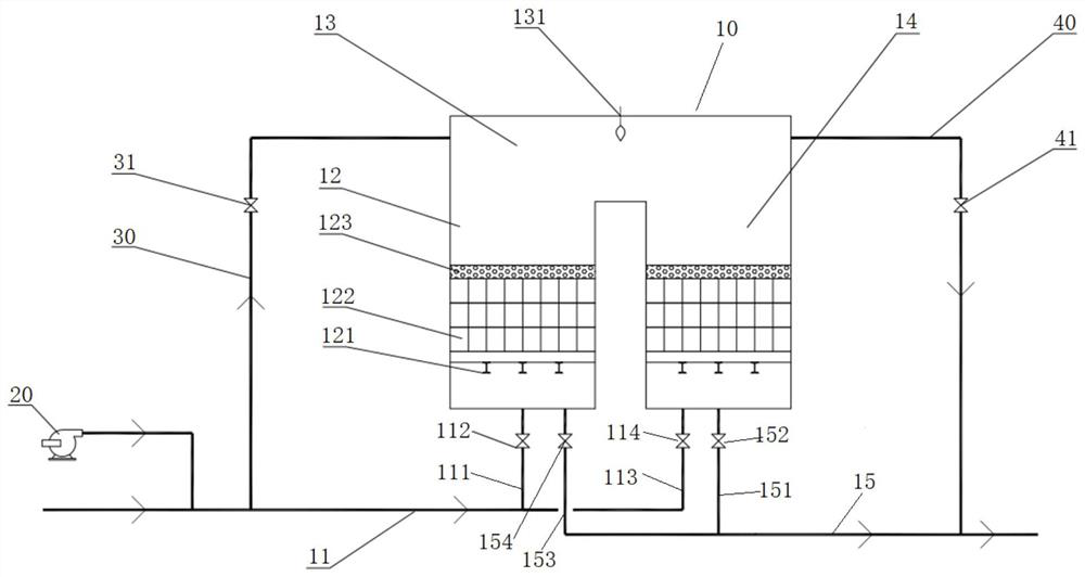
[0039] Such as figure 1 As shown, the regenerative thermal oxidation device for treating electroplating sludge sintering waste gas provided by the present invention includes a regenerative thermal oxidation furnace 10 and a frequency conversion fresh air fan 20 . The regenerative thermal oxidation furnace 10 is a two-chamber RTO, including an inlet pipe 11 , a first regenerator 12 , a combustion chamber 13 , a second regenerator 14 , and an outlet pipe 15 . The inlet pipeline 11 is divided into a first inlet pipeline 111 connected with the first regenerator 12 and a second inlet pipeline 113 connected with the second regenerator 14, and a first inlet switching valve 112 is arranged on the first inlet pipeline 111. A se...


PUM


Abstract

The invention relates to a regenerative thermal oxidation device and process for processing electroplating sludge sintering waste gas. The temperature of the inlet waste gas entering an RTO heat storage bed and the flow rate of the waste gas flowing through the heat storage bed are flexibly adjusted by arranging an inlet fresh air fan. An RTO cold bypass regulating pipeline and heat bypass regulating pipeline are arranged to flexibly adjust the heat load distribution, so as to adjust the temperature of an RTO regenerator and combustion chamber and improve the heat recovery efficiency. Throughthe fresh air fan and the cold and heat bypass adjustment, the organic silicon burned in the middle of the heat storage body can be avoided, and at the same time, a replacement layer is arranged on the top of the heat storage bed to solve the problem that the bed is blocked and difficult to clean. Through targeted improvement of the RTO device and process, the regenerative thermal oxidation deviceand process can adapt to the characteristics of electroplating sludge sintering waste gas, solve existing practical problems, realize long-term safe and efficient operation, meet the requirements ofemission standards, remove more than 99% volatile organic compounds, and have good economic and environmental benefits.

Description

technical field [0001] The invention relates to the technical field of waste gas treatment, in particular to a regenerative thermal oxidation (hereinafter referred to as RTO) device and process for treating electroplating sludge sintering waste gas. Background technique [0002] Due to the complex composition of electroplating sludge sintering waste gas, in addition to dust, sulfur oxides, nitrogen oxides and other pollutants, there are also combustible components (including volatile organic compounds, carbon monoxide, etc.) with large calorific value fluctuations and low spontaneous ignition components. Due to the characteristics of high ratio and organic silicon components, it is not possible to simply apply existing mature technologies in other industries, and it is necessary to develop a suitable technical route according to the actual situation of the industry. [0003] At present, domestic electroplating sludge sintering devices are generally only equipped with dust re...

Claims


Application Information

Patent Timeline
Patent Type & Authority Applications(China)
IPC IPC(8): F23G7/06F23G5/44F28D20/00
CPCF23G5/44F23G7/06F28D20/0056Y02E60/14
Inventor 吴敏韩长民张轶丁后亮薛菲
Owner WUHAN KAIDI ELECTRIC POWER ENVIRONMENTAL
Why Eureka
Try Eureka