Respirator and working method thereof

A ventilator and casing technology, applied to ventilators and their work fields, can solve the problems of difficult exhalation of patients, limited oxygen volume, discomfort of patients, etc., and achieve the effect of saving labor intensity.

Pending Publication Date: 2020-10-13
耿超玮
View PDF0 Cites 0 Cited by
  • Summary
  • Abstract
  • Description
  • Claims
  • Application Information

AI Technical Summary

Problems solved by technology

[0003] There are more and more types of existing ventilators, and the operation is more and more simple, and all can provide the patient with the oxygen needed to maintain the illness, but there are still the following defects: 1. The oxygen source of the existing ventilators mainly comes from oxygen Oxygen bottle, that is, to input oxygen to the patient's airway port through the oxygen bottle, but the amount of oxygen stored in the oxygen bottle is limited. The patient has a short-term feeling of dyspnea, and because the oxygen cylinder is large in size and heavy in weight, the oxygen cylinder is also very troublesome, which increases the work intensity
2. The oxygen stored in the oxygen cylinder is dry, and after the patient inhales oxygen, the function of the patient's nasal cavity decreases, because the oxygen reaching the patient's lungs has no humidity, which brings discomfort to the patient
3. There is a breathing mask connected to the end port of the ventilator. Since the breathing mask fits closely with the patient's face, it is difficult for the patient to discharge the exhaled gas into the atmosphere when exhaling, making the patient feel suffocated and giving the patient a sense of suffocation. Difficulty with breathing out

Method used


Image

  • Respirator and working method thereof
  • Respirator and working method thereof
  • Respirator and working method thereof

Examples


Embodiment Construction

[0035] The present invention will be further described below in conjunction with the accompanying drawings. The protection scope of the present invention is not limited to the following:

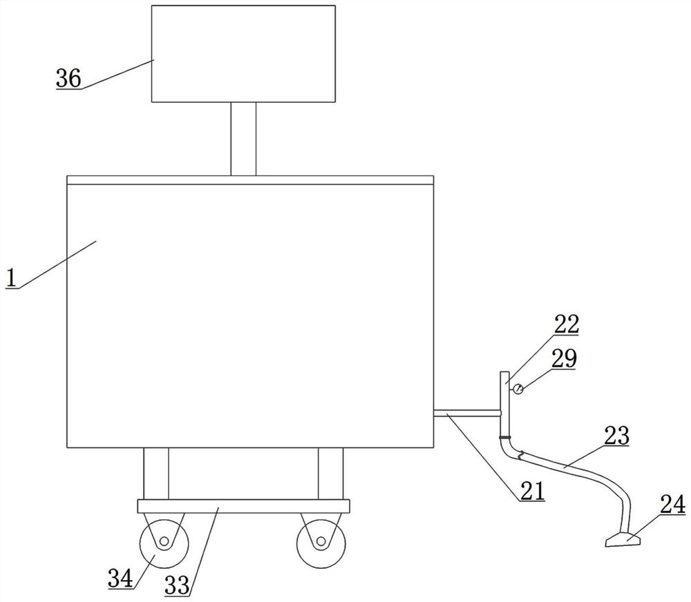
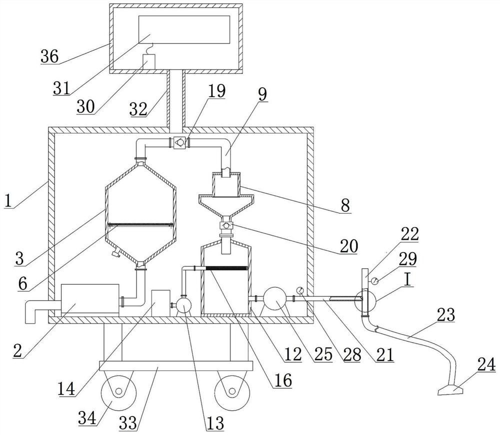
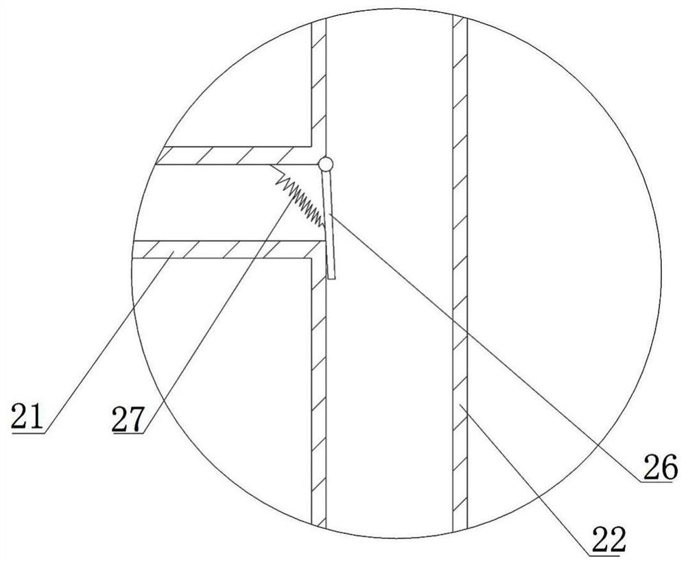
[0036] Such as Figure 1~7 As shown, a ventilator includes a casing 1, which is provided with an oxygen generating device, an oxygen filtering device and an oxygen humidifying device, and the oxygen generating device includes an air compressor 2 and an oxygen generating tank 3. The upper and lower ends of the oxygen generating tank 3 are respectively provided with an air outlet 4 and an air inlet 5, and an exchange membrane 6 is arranged in the oxygen generating tank 3. The exchange membrane 6 separates the oxygen generating tank 3 into an upper chamber and a lower chamber, and generates oxygen. A safety valve 7 is provided on the side wall of the tank 3, and the safety valve 7 communicates with the lower chamber. The air compressor 2 is fixed at the bottom of the casing 1, and the outlet end o...


PUM


Abstract

The invention discloses a respirator. The respirator comprises a machine shell, wherein an oxygen generating device, an oxygen filtering device and an oxygen humidifying device are arranged in the machine shell; the oxygen generating device comprises an air compressor and an oxygen generating tank; an air outlet and an air inlet are formed in the upper end and the lower end of the oxygen generating tank respectively; an exchange membrane is arranged in the oxygen generating tank; the exchange membrane divides the oxygen generation tank into an upper cavity and a lower cavity; a safety valve isarranged on the side wall of the oxygen generating tank and communicates with the lower cavity; and the air compressor is fixedly arranged at the bottom of the machine shell, and the outlet end of the air compressor is connected with the air inlet through a pipeline. The beneficial effects have the advantages that the structure is compact, suffocation feeling is avoided, oxygen can be moistened,oxygen can be generated automatically, and an oxygen bottle does not need to be replaced.

Description

Technical field [0001] The invention relates to the technical field of ventilator structures, in particular to a ventilator and its working method. Background technique [0002] In modern clinical medicine, the ventilator, as an effective means to artificially replace the autonomous ventilation function, has been commonly used in various reasons for respiratory failure, anesthesia breathing management during major operations, respiratory support treatment and emergency recovery. It occupies a very important position in the field of modern medicine. The ventilator is a vital medical device that can prevent and treat respiratory failure, reduce complications, and save and prolong the lives of patients. The basic principle of the ventilator: the inhalation action produces negative pressure in the chest cavity during autonomous ventilation, and the negative pressure of the alveoli and airway occurs when the lungs are passively expanded, which constitutes the pressure difference betw...

Claims


Application Information

Patent Timeline
Patent Type & Authority Applications(China)
IPC IPC(8): A61M16/00A61M16/10A61M16/12A61M16/16
CPCA61M16/00A61M16/105A61M16/12A61M16/16A61M2016/003A61M2205/3334A61M2205/75
Inventor 耿超玮
Owner 耿超玮
Why Eureka
Try Eureka