
Method for removing hydrogen impurities in CO feed gas by using three-stage catalyst filling method

A catalyst and raw material gas technology, which is applied in the field of dehydrogenation purification process of CO raw material gas in the coal-to-ethylene glycol technology, can solve the problems of high operating energy consumption, many hidden dangers in equipment safety, and high manufacturing cost, and achieves the improvement of reaction temperature, The effect of reducing the risk of high temperature sintering and improving the efficiency of low temperature dehydrogenation

Active Publication Date: 2020-10-13
FUJIAN INST OF RES ON THE STRUCTURE OF MATTER CHINESE ACAD OF SCI
View PDF9 Cites 0 Cited by
  • Summary
  • Abstract
  • Description
  • Claims
  • Application Information

AI Technical Summary

Problems solved by technology

However, in industrial scale-up production, this type of reactor has problems such as high manufacturing cost, cumbersome process, high energy consumption in operation, and many equipment safety hazards, so it is difficult to apply to actual production
[0005] In order to solve the problems of reaction heat effect and side reactions difficult to control in the CO raw material gas selective oxidation dehydrogenation purification process, the present invention aims to develop a process method that is highly compatible with the reaction process

Method used


Image

  • Method for removing hydrogen impurities in CO feed gas by using three-stage catalyst filling method

Examples


Embodiment 1

[0021] Preparation of three catalysts:

[0022] Weigh Al 2 O 3 The powder was placed in a palladium active component solution with a concentration of 0.02mol / L for 6h; after filtration, the product was placed in an oven at 100°C for drying for 10h, and then placed in a muffle furnace for calcination at 250°C for 8h; the calcined product was mixed with chloride Ammonium was mixed in a molar ratio of 1:0.2 and then placed in H 2 PdCl was obtained by treating at 350℃ for 3h in the atmosphere x / Al 2O 3 , marked as GL-1, in which the mass percentage of Pd is 1 wt%.

[0023] Weigh CeO 2 20wt% CeO 2 -Al 2 O 3 The powder was placed in a palladium active component solution with a concentration of 0.02mol / L for 20h; after filtration, the product was dried in an oven at 100°C for 10h, and then placed in a muffle furnace for calcination at 450°C for 8h; the calcined product was soaked in Stir in NaOH-NaHCO3 solution with a concentration of 0.1mol / L for 6h, filter and dry it and...

Embodiment 2

[0029] The preparation method of the catalyst is the same as that in Example 1.

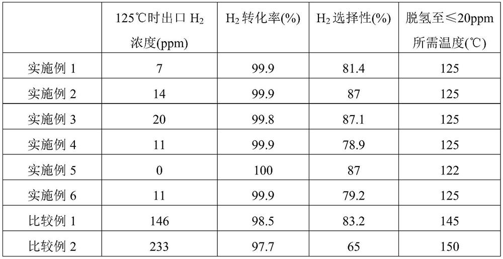
[0030] Three-stage removal of H in CO feed gas 2 Impurities: The catalyst is filled according to the ratio of Pd moles: GL-1=25%, GL-2=50%, GL-3=25%, and 12.5g GL-3, 25g GL-2, 12.5g GL are filled in sequence -1 into the bed, others are the same as in Example 1. The catalyst dehydrogenation results are shown in Table 1.

Embodiment 3

[0032] The preparation method of the catalyst is the same as that in Example 1.

[0033] Three-stage removal of H in CO feed gas 2 Impurities: The catalyst is filled according to the ratio of Pd moles: GL-1=15%, GL-2=70%, GL-3=15%, and fill 7.5g GL-3, 35g GL-2, 7.5g GL in sequence -1 into the bed, others are the same as in Example 1. The catalyst dehydrogenation results are shown in Table 1.


PUM


Abstract

The invention provides a method for removing H2 impurities in CO feed gas by using a three-stage catalyst filling method. According to the change trend of the concentrations of reactants and productsin the whole catalyst bed layer and the difference of reaction heat effects, three catalysts with specific chemical structures and properties are designed and selected, the three catalysts are packedin different concentration intervals of a reaction bed layer according to a specific sequence and specific proportions, and reaction heat effect and a side reaction rate are synergistically controlledby utilizing respective chemical properties of the three catalysts. According to the method for removing H2 impurities in CO feed gas by using the three-stage catalyst filling method in the invention, on the basis that catalyst preparation cost and process equipment cost are not increased, the reaction temperature of the catalyst is reduced to 125-130 DEG C from 145-150 DEG C in the prior art, soenergy consumption can be substantially reduced, the thermal sintering risk of the catalyst is reduced, and the service life and the replacement period of the industrial catalyst can be easily prolonged; and the method has large-scale industrial application prospects.

Description

technical field [0001] The invention belongs to the technical field of coal-to-ethylene glycol, and is suitable for dehydrogenation and purification processes of CO raw material gas obtained from fossil resources or organic matter as raw materials, such as coal gasification, methanol cracking, methane reforming, etc., and is especially suitable for coal-to-ethylene glycol technology Dehydrogenation purification process of medium CO feed gas. Background technique [0002] In the implementation process of coal-to-ethylene glycol technology, coal first needs to be reformed by gasification to obtain CO / H 2 The mixed gas is then separated by pressure swing adsorption to obtain CO raw material gas. However, due to the restriction of separation efficiency and other factors, there is still a certain concentration of H in the CO feed gas obtained at this time. 2 impurities. In order to avoid the problems of catalyst deactivation and increase of by-products during CO oxidative coup...

Claims


Application Information

Patent Timeline
Patent Type & Authority Applications(China)
IPC IPC(8): C01B32/40C01B5/00C01B32/50
CPCC01B5/00C01B2210/0004C01B2210/0053C01B32/40C01B32/50
Inventor 姚元根乔路阳周张锋宗珊珊崔国静吴娟许东杰
Owner FUJIAN INST OF RES ON THE STRUCTURE OF MATTER CHINESE ACAD OF SCI
Learn More