Gas detection device and gas detection method

A detection device, gas technology, applied in chemical instruments and methods, mixers with rotary stirring devices, transportation and packaging, etc., to achieve the effect of improving detection accuracy

Active Publication Date: 2020-10-13
南京三鸣智自动化工程有限公司
View PDF26 Cites 0 Cited by
  • Summary
  • Abstract
  • Description
  • Claims
  • Application Information

AI Technical Summary

Problems solved by technology

[0003] The first purpose of the present invention is to provide a gas detection device to overcome the problem that the prior art directly detects high-concentration gases and easily produces large errors

Method used


Image

  • Gas detection device and gas detection method
  • Gas detection device and gas detection method
  • Gas detection device and gas detection method

Examples


Embodiment

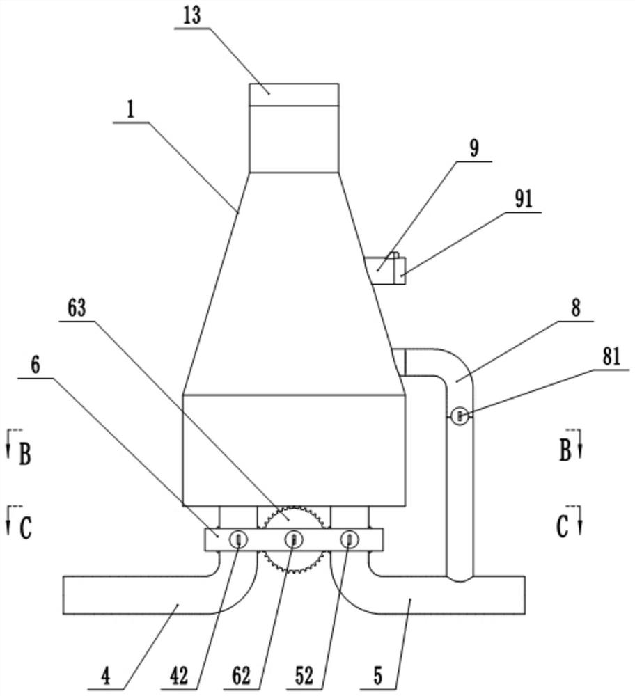
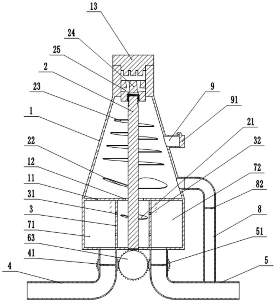
[0033] A gas detection device, such as figure 1 with 2 As shown, it includes the gas delivery equipment to be tested, the catalytic gas delivery equipment, the mixer 1 and the catalytic combustion sensor 13, the catalytic combustion sensor 13 is installed on the top of the mixer 1, and the top of the mixer 1 is equipped with a device to guide the mixed gas to catalytic combustion. The guide notch of sensor 13, the plunger 24 that is used to close guide notch is slidably installed in the guide notch, is formed with some gas passages 25 in the plunger 24, and the air inlet of gas passage 25 is positioned at the side wall of plunger 24, and gas The gas outlet of the passage 25 is located at the top of the plunger 24 and communicates with the guide notch, and the inner diameter of the gas passage 25 gradually increases from the inlet to the outlet.

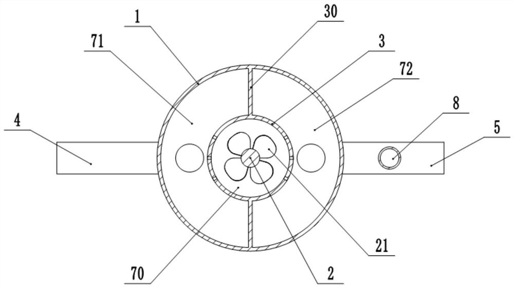
[0034] Such as figure 1As shown, the mixer 1 is provided with a partition plate 11, which divides the interior of the mixer 1 from...


PUM


Abstract

The invention relates to the technical field of gas detection. The invention discloses a gas detection device and a gas detection method. The detection device comprises a mixer, to-be-detected gas conveying equipment, catalysis assisting gas conveying equipment and a catalytic combustion sensor. A flow guide area and a mixing area are arranged in the mixer; a premix area, a first gas guide area and a second gas guide area are formed in the mixing area; the to-be-detected gas conveying equipment is connected with the first gas guide area, the catalysis assisting gas conveying equipment is connected with the second gas guide area and can convey catalysis-assisting gas into the premix area, the to-be-detected gas and the catalysis-assisting gas are mixed in the premix area to form mixed gas,and the mixed gas is guided to the catalytic combustion sensor through the flow guide area. The detection method comprises the following steps: S1, conveying to-be-detected gas and catalysis-assistinggas into a mixer for mixing to obtain a to-be-detected gas sample; and S2, detecting the to-be-detected gas sample through a catalytic combustion sensor to obtain a combustible gas concentration value.

Description

technical field [0001] The invention relates to the technical field of gas detection, in particular to a gas detection device and a detection method. Background technique [0002] In order to ensure safety in industrial production and testing, it is necessary to detect the concentration of some gases in the flue used in industrial production. When the traditional technology detects the gas concentration of the gas in the flue, infrared gas detectors are often used. However, due to the high gas concentration in the flue during use, it is easy to cause the gas concentration data detected by the infrared gas detector to be different from the real gas. Concentration produces a large error. Contents of the invention [0003] The first object of the present invention is to provide a gas detection device, so as to overcome the problem in the prior art that direct detection of high-concentration gas is prone to large errors. [0004] In order to achieve the above object, the bas...

Claims


Application Information

Patent Timeline
Patent Type & Authority Applications(China)
IPC IPC(8): G01N31/10G01N31/12B01F7/16B01F7/24
CPCG01N31/10G01N31/12B01F27/55B01F27/87B01F27/923B01F27/92B01F35/3203B01F2101/23
Inventor 李智李家豪张国庆
Owner 南京三鸣智自动化工程有限公司
Why Eureka
Try Eureka