
Piezoresistive triaxial accelerometer

A shaft acceleration and piezoresistive technology, applied in the field of sensors, can solve problems such as complex processing technology, complex packaging structure, and large coupling between shafts, and achieve the effects of reducing coupling between shafts, improving measurement accuracy, and reducing system errors

Pending Publication Date: 2020-10-13
HUZHOU JOUKING ELECTRONICS
View PDF0 Cites 2 Cited by
  • Summary
  • Abstract
  • Description
  • Claims
  • Application Information

AI Technical Summary

Problems solved by technology

[0005] The purpose of the present invention is to provide a three-axis piezoresistive accelerometer, the present invention solves the existing three-axis accelerometer low sensitivity, large inter-axis coupling, complex packaging structure, and low yield due to complex processing technology question

Method used


Image

  • Piezoresistive triaxial accelerometer
  • Piezoresistive triaxial accelerometer
  • Piezoresistive triaxial accelerometer

Examples


Embodiment Construction

[0025] The present invention will be further described below with reference to the accompanying drawings.

[0026] Various exemplary embodiments of the present invention will now be described in detail with reference to the accompanying drawings. It should be noted that the relative arrangements of components and steps, numerical expressions and numerical values ​​set forth in these embodiments do not limit the scope of the present invention unless specifically stated otherwise.

[0027] The following description of the exemplary embodiments is merely illustrative in nature and in no way taken as any limitation of the invention and its application or uses. In all examples shown and discussed, any specific values ​​should be construed as exemplary only, and not as limitations. Therefore, other instances of the exemplary embodiment may have different values.

[0028] Techniques, methods and devices known to those of ordinary skill in the relevant art may not be discussed in de...


PUM


Abstract

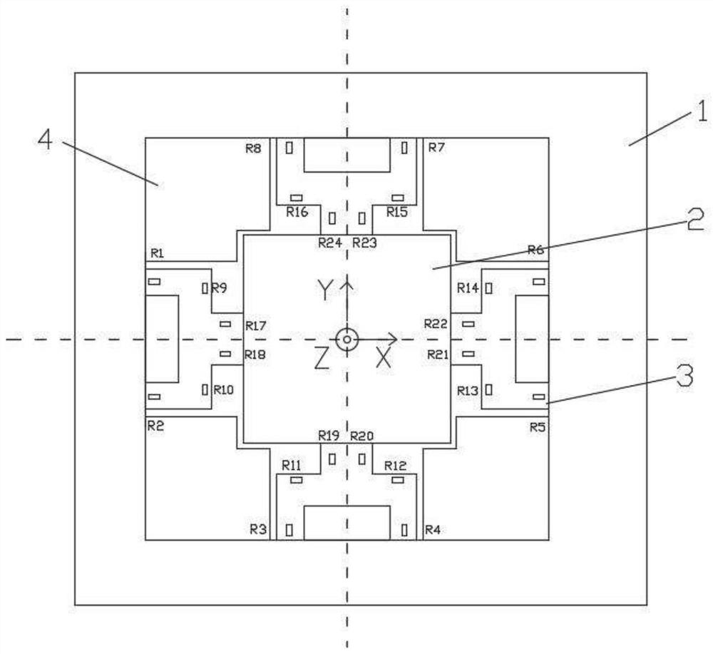
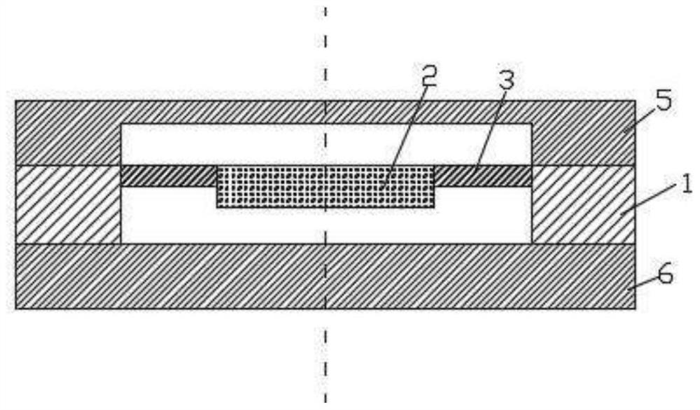
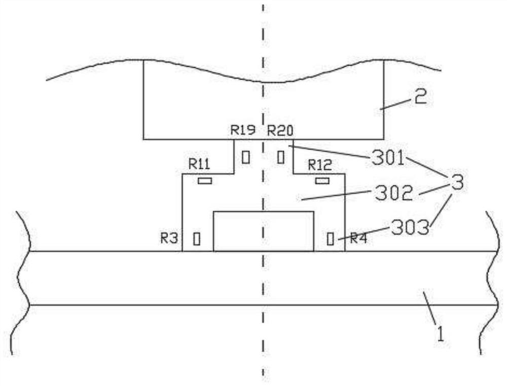
The invention discloses a piezoresistive triaxial accelerometer. The piezoresistive triaxial accelerometer comprises a supporting frame, a mass block, and an elastic cantilever beam; the mass block issuspended at the central position of the support frame through the elastic cantilever beam; a plurality of strain piezoresistors with equal resistance values are symmetrically distributed on the elastic cantilever beam between the support frame and the mass block; limiting modules are arranged at the four inner corners of the supporting frame correspondingly. X-direction anti-overload gaps and Y-direction anti-overload gaps are formed between the limiting modules and the adjacent elastic cantilever beams and between the limiting modules and the mass blocks, an upper cover plate and a lower cover plate are arranged on the upper side and the lower side of the supporting frame respectively, and Z-direction anti-overload gaps are formed between the mass blocks and the lower cover plate and between the mass blocks and the upper cover plate. The piezoresistive triaxial accelerometer has higher sensitivity, accuracy and rigidity, facilitates resetting of the mass block, reduces system errors, improves measurement precision and reduces interaxial coupling of the accelerometer.

Description

technical field [0001] The invention relates to the technical field of sensors, in particular to a three-axis piezoresistive accelerometer. Background technique [0002] As an inertial device, accelerometers are widely used in aerospace, transportation, automatic control, biology, chemistry, medical analysis and vibration testing and other fields. With the development and promotion of Industry 4.0, accelerometers are developing in the direction of miniaturization, integration, high reliability and high sensitivity. Accelerometers currently have piezoresistive, piezoelectric, capacitive, tunnel and other types. Among them, the piezoresistive accelerometer has been widely used due to its small size, high sensitivity, good stability, good dynamic response characteristics and output, wide frequency range, low mass production cost, and good compatibility with silicon integrated circuit planar technology. favor. [0003] At present, most single accelerometers on the market can ...

Claims


Application Information

Patent Timeline
Patent Type & Authority Applications(China)
IPC IPC(8): G01P15/12
CPCG01P15/12
Inventor 维尼特·辛格内丘克武克里斯·韦金亚陈林峰潘峰
Owner HUZHOU JOUKING ELECTRONICS
Learn More