Binding post machining device and method

A processing device and processing method technology, applied to electrical components, relays, circuits, etc., can solve the problems of reducing sheet resistance, destroying the surface layer, and unable to completely remove the surface layer of the terminal, so as to ensure contact performance and reduce contact resistance , The effect of reducing the sheet resistance

Active Publication Date: 2020-10-13
KUNSHAN LIANTAO ELECTRONICS CO LTD
View PDF11 Cites 0 Cited by
  • Summary
  • Abstract
  • Description
  • Claims
  • Application Information

AI Technical Summary

Problems solved by technology

[0004] In the prior art, the way to reduce the contact resistance is to use a tungsten steel brush to polish the terminal, destroy part of the surface layer at the contact position of the terminal, and reduce the sheet resistance, thereby reducing the contact resistance. However, this method cannot completely remove the contact resistance. The surface layer of the column cannot effectively reduce the contact resistance

Method used


Image

  • Binding post machining device and method
  • Binding post machining device and method
  • Binding post machining device and method

Examples


Embodiment 1

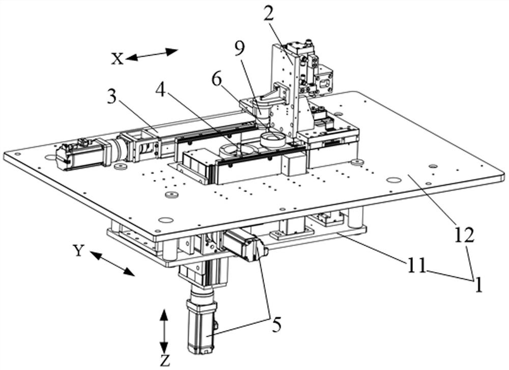
[0049] This embodiment provides a terminal post processing device, capable of milling the terminal post, so that the sheet resistance of the post-processed post can be reduced, thereby reducing the contact resistance of the relay.

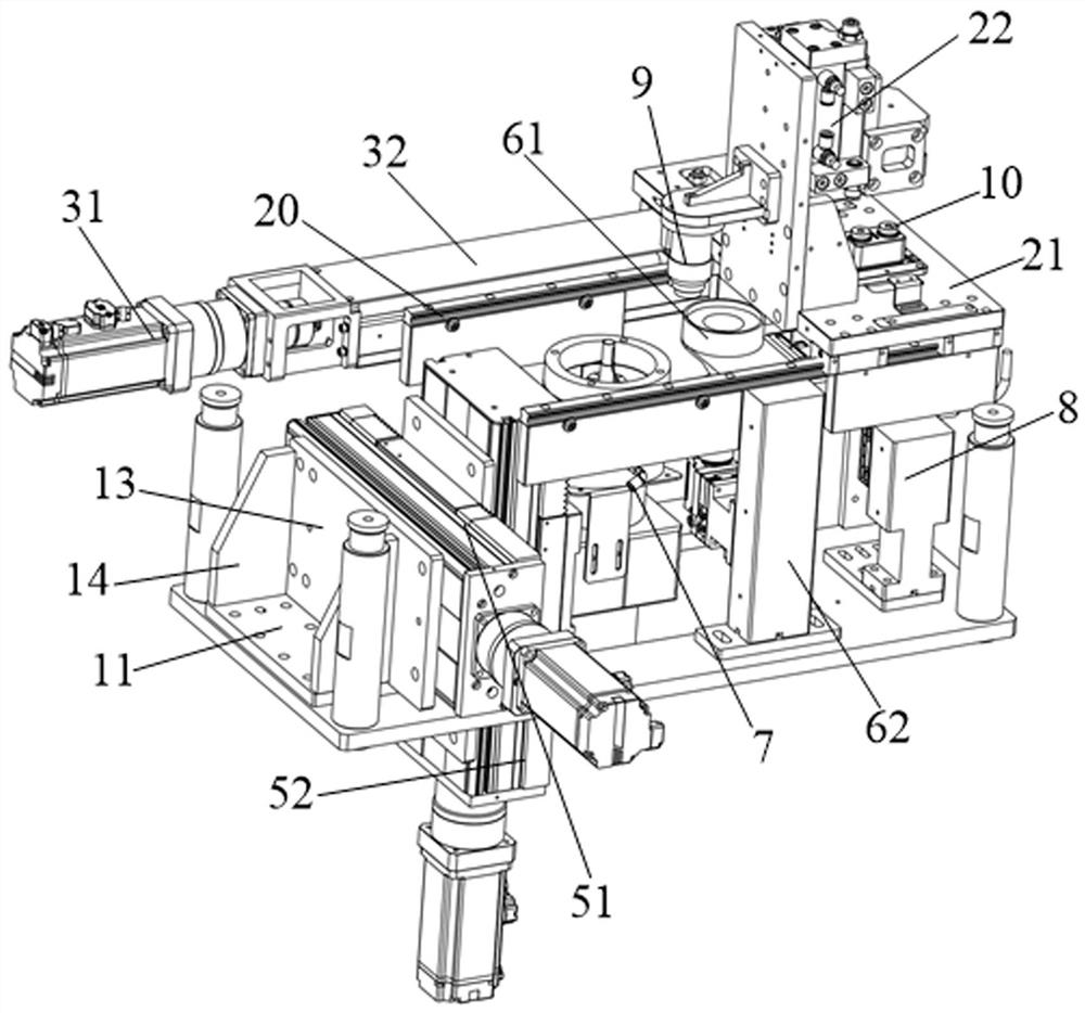
[0050] Such as Figure 1 to Figure 5 As shown, the terminal post processing device includes a fixing seat 1 , a product fixing structure 2 , a first driving mechanism 3 , a milling mechanism 4 and a second driving mechanism 5 . The fixing seat 1 includes a base plate 11 , a fixing plate 12 , a side plate 13 and a reinforcing plate 14 . Wherein, the bottom plate 11 and the fixed plate 12 are fixedly connected by the fixed column, the side plate 13 is connected between the bottom plate 11 and the fixed plate 12, and the reinforcement plate 14 is respectively connected with the bottom plate 11 and the side plate 13, and is used to increase the size of the bottom plate 11 and the side plate. 13 between connection strengths.

[0051] Wherein, the prod...

Embodiment 2

[0067] This embodiment provides a terminal post processing method, which can be applied to the terminal post processing device in the first embodiment, such as Figure 6 As shown, the terminal post processing method includes the following steps:

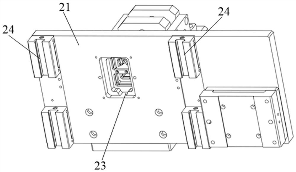
[0068] S1. Fix the ceramic component 30 on the product fixing structure 2 , and control the bottom end of the terminal post 10 in the ceramic component 30 to pass through the through hole 23 on the product fixing structure 2 .

[0069] The ceramic component 30 can be manually fixed on the product fixing structure 2, and the bottom end of the terminal 10 can be passed through the through hole 23, and the ceramic component 30 can also be fixed on the product fixing structure 2 by a manipulator, and the terminal The bottom end of 10 passes through the through hole 23 .

[0070] S2. Drive the product fixing structure 2 to move in the first horizontal direction X through the first driving mechanism 3, so that the plane where the axis of ...


PUM


Abstract

The invention discloses a binding post machining device and method. The binding post machining device comprises a fixing base, a product fixing structure, a first driving mechanism, a milling mechanism, and a second driving mechanism. The product fixing structure is arranged on the fixing base in a sliding mode, a through hole is formed in the product fixing structure, and the bottom end of a binding post can penetrate through the through hole; the first driving mechanism is arranged on the fixing base and used for driving the product fixing structure to move in a first horizontal direction; the milling mechanism is arranged on the fixing base and is used for milling the bottom end of the binding post, so that oxygen-free copper in the bottom end of the binding post is exposed; and the second driving mechanism is arranged on the fixing base, is connected with the milling mechanism and is used for driving the milling mechanism to move in a second horizontal direction and a vertical direction. According to the invention, oxygen-free copper at the bottom ends of the binding posts can be exposed, so that the sheet resistance of the binding posts is reduced, and the contact resistance of the relay can be effectively reduced; and the consistency of the vertical distance between the top surfaces of the binding posts and the connecting ring can be ensured when the bottom ends of a plurality of binding posts are milled.

Description

technical field [0001] The invention relates to the technical field of relay manufacturing, in particular to a terminal post processing device and a processing method. Background technique [0002] A relay is a controller that can be used in electric commercial vehicles, electric passenger cars or charging stations. At present, the working principle of the relay is that the contact bridge moves upward under the drive of the driving mechanism and contacts with two terminals. The position where the contact bridge contacts the terminals is called a contact. When the contacts are closed, the two terminals are turned on. [0003] There is a contact resistance in the working process of the relay, which is also called contact resistance. Among them, the contact resistance includes two parts, which are compressive resistance and sheet resistance. Compression resistance is the increase in resistance of metal contacts due to the compression of current. Sheet resistance is the conta...

Claims


Application Information

Patent Timeline
IPC IPC(8): H01H49/00
CPCH01H49/00
Inventor 不公告发明人
Owner KUNSHAN LIANTAO ELECTRONICS CO LTD
Why Eureka
Try Eureka