
Solar photovoltaic panel convenient to adjust

A solar photovoltaic panel and installation panel technology, applied in the field of solar photovoltaic panels, can solve problems such as poor maintainability, imperfect structural design, and few adjustment angles, so as to improve maintainability and operational stability, and improve photovoltaic power generation efficiency and quality effects

Pending Publication Date: 2020-10-13
李明
View PDF14 Cites 4 Cited by
  • Summary
  • Abstract
  • Description
  • Claims
  • Application Information

AI Technical Summary

Problems solved by technology

There are many kinds of solar photovoltaic panels on the market at present, but there are generally disadvantages of inconvenient adjustment. The existing solar photovoltaic panels are all fixed installations. Due to changes in the angle of sunlight, they sometimes cannot receive light, and It is very troublesome to make an adjustment
[0003] Chinese patent (notification number CN210490779U) discloses a solar photovoltaic panel that is easy to adjust. Although the height and angle can be adjusted, the structural design of the adjustment is not perfect, resulting in less adjustment angles and poor maintainability.

Method used


Image

  • Solar photovoltaic panel convenient to adjust
  • Solar photovoltaic panel convenient to adjust
  • Solar photovoltaic panel convenient to adjust

Examples


Embodiment 1

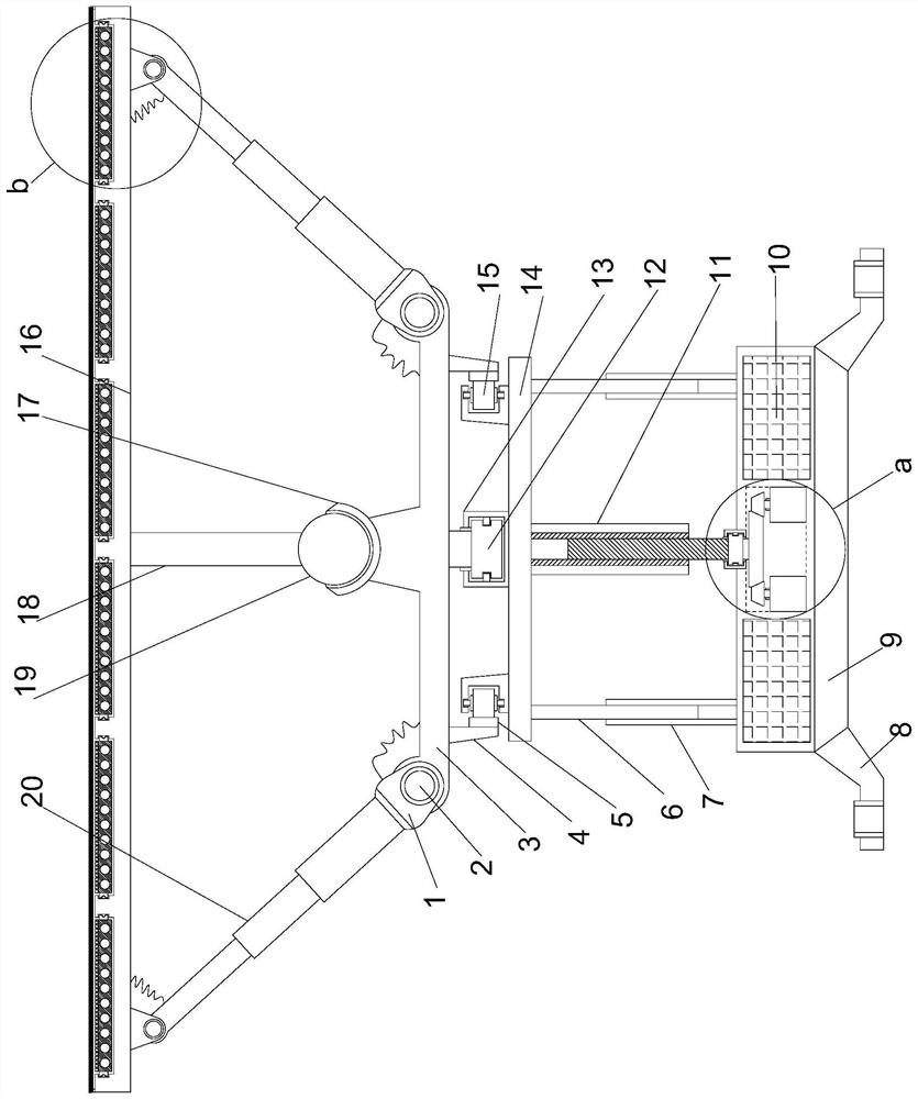
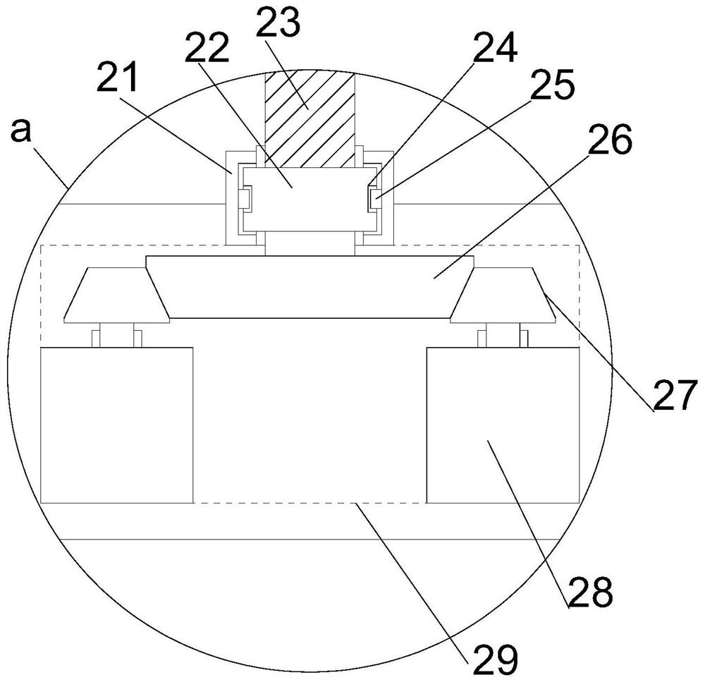
[0022] see Figure 1~4 , in an embodiment of the present invention, a solar photovoltaic panel that is easy to adjust includes a support mounting plate 9 arranged horizontally, and several fixed mounting frames 8 are arranged at equal angles on the lower end edge of the support mounting plate 9, and the fixed mounting frames 8 are all vertical A fixed mounting cylinder is provided, a lifting mounting plate 14 is horizontally arranged directly above the supporting mounting plate 9, a rotating mounting plate 3 is horizontally disposed directly above the lifting mounting plate 14, and a transmission shaft is vertically arranged at the middle position of the supporting mounting plate 9. Mounting cavity 29, the supporting mounting plate 9 on both sides of the transmission mounting cavity 29 is embedded with a storage battery 10, and the upper middle position of the transmission mounting cavity 29 is vertically provided with a limit bearing sleeve 21, and the limit bearing sleeve 21 ...

Embodiment 2

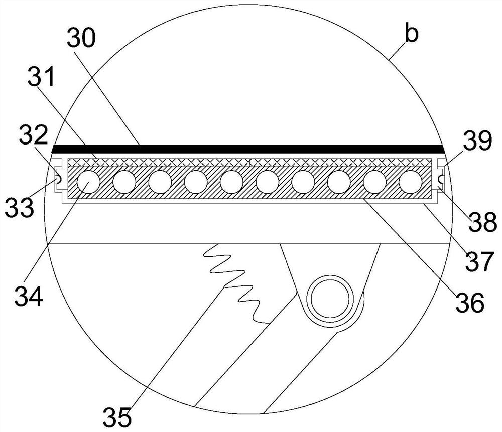
[0025] On the basis of Embodiment 1, through the cooperation of the directional installation groove 39 and the directional installation column 38, the replacement of the directional installation plate 36 and the photovoltaic power generation panel 31 on it is realized, and the maintainability of the device is improved, and the conduction and heat dissipation arranged at equal intervals The holes 34 can reduce the temperature of the illuminated surface of the device, improve the stability of the photovoltaic power generation panel 31 , and thus improve the stability of the power generation of the device.


PUM


Abstract

The invention relates to the field of new energy, in particular to a convenient-to-adjust solar photovoltaic panel. The solar photovoltaic panel comprises a supporting mounting plate which is horizontally arranged, a plurality of fixed mounting frames are arranged on the lower end edge of the supporting mounting plate at equal angles; fixed mounting cylinders are vertically arranged on the fixed mounting frames; a lifting mounting plate is horizontally arranged over the supporting mounting plate, a rotary mounting plate is horizontally arranged right above the lifting mounting plate; a transmission mounting cavity is vertically formed in the middle position of the supporting mounting plate; the lifting of a stud and a screw cylinder is controlled, the steering control of a gear ring is realized, the swing control is achieved through swing telescopic structures arranged at equal angles, so that the angle, the height and the steering direction of a photovoltaic power generation device can be efficiently and accurately adjusted, the photovoltaic power generation efficiency and quality of the device are remarkably improved, and the maintainability and the operation stability of the device are improved through flow guide heat dissipation and interchangeable installation.

Description

technical field [0001] The invention relates to the field of new energy, in particular to a solar photovoltaic panel which is easy to adjust. Background technique [0002] Photovoltaic panel module is a power generation device that generates direct current when exposed to sunlight. It is composed of thin solid photovoltaic cells almost entirely made of semiconductor materials. Since there are no moving parts, it can be operated for a long time without causing any damage. Simple photovoltaic cells can power watches and computers, and more complex photovoltaic systems can light houses and supply electricity to the grid. There are many kinds of solar photovoltaic panels on the market at present, but there are generally disadvantages of inconvenient adjustment. The existing solar photovoltaic panels are all fixed installations. Due to changes in the angle of sunlight, they sometimes cannot receive light, and It is very troublesome to make an adjustment. [0003] Chinese patent...

Claims


Application Information

Patent Timeline
Patent Type & Authority Applications(China)
IPC IPC(8): H02S20/30H02S40/30H02S40/42F24S25/13F24S30/20F24S30/425
CPCH02S20/30H02S40/30H02S40/42F24S25/13F24S30/20F24S30/425Y02E10/47Y02E10/50
Inventor 李明
Owner 李明
Learn More