Temperature compensation attenuator

A technology of temperature compensation and attenuator, which is applied in network improvement, multi-terminal pair network, frequency selection two-terminal pair network, etc. to reduce the influence of temperature changes, and can solve the problems of deteriorating high and low temperature gain flatness and attenuation increase

Pending Publication Date: 2020-10-13
CHINA ELECTRONICS TECH GRP CORP NO 14 RES INST
View PDF0 Cites 2 Cited by
  • Summary
  • Abstract
  • Description
  • Claims
  • Application Information

AI Technical Summary

Problems solved by technology

At the same time, attenuators are widely used in radio frequency systems. As the temperature rises, the atten

Method used


Image

  • Temperature compensation attenuator
  • Temperature compensation attenuator
  • Temperature compensation attenuator

Examples


Embodiment Construction

[0019] The technical solution of the present invention will be specifically described below in conjunction with the accompanying drawings.

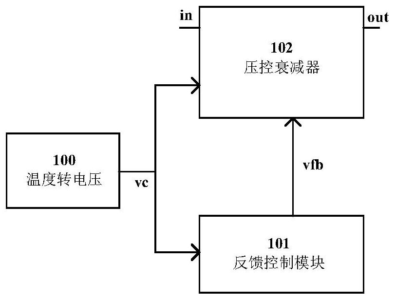
[0020] The structure of the attenuator is as figure 1 As shown, it includes three modules: temperature-to-voltage module, feedback control module, and voltage-controlled attenuator. The temperature-to-voltage module outputs control signals to the feedback control module and voltage-controlled attenuator, and the feedback control module outputs feedback control signals to the voltage-controlled attenuator. Voltage, the signal to be processed is processed by a voltage-controlled attenuator to eliminate the influence of gain changes caused by temperature changes.

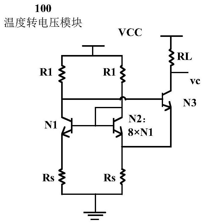
[0021] The main circuit of the temperature-to-voltage module 100 is as follows: figure 2 As shown, a typical bandgap reference circuit is composed of resistors R1, Rs, RL and transistors N1, N2, N3. Transistor N2 is composed of 8 transistors N1 connected in parallel, and the num...


PUM


Abstract

The invention discloses a temperature compensation attenuator, which is applied to a radio frequency system along with temperature rise and attenuation drop under the condition of keeping matching, and can realize the effect of compensating high and low temperature gain changes of other radio frequency modules, so that the high and low temperature gain of a transceiving link is flat, and the design difficulty of high and low temperature application of the radio frequency system is reduced.

Description

technical field [0001] The invention belongs to the technical field of integrated circuit design and manufacture, and specifically relates to a voltage control and feedback technology. Background technique [0002] With the rapid development of communication systems, the application environment of communication products is becoming more and more complex. The high and low temperature working environment and the heat generation of the product itself put forward higher requirements for the high and low temperature design of the chip. The gain of the signal transceiver link varies with temperature. The stability requirements of changes are also getting higher and higher. In general, as the temperature rises, the gain of the transceiver link continues to decrease, and reducing the gain gap between high and low temperatures has become one of the design difficulties. At the same time, attenuators are widely used in radio frequency systems. As the temperature rises, the attenuation...

Claims


Application Information

Patent Timeline
IPC IPC(8): H03H11/54H03H11/06
CPCH03H11/54H03H11/06Y02D30/70
Inventor 周阳阳张浩竺磊
Owner CHINA ELECTRONICS TECH GRP CORP NO 14 RES INST
Why Eureka
Try Eureka