Ulna olecranon morphological anatomy locking method and steel plate structure

A technology of olecranon and steel plate of the ulna, applied in the directions of outer plate, fixator, internal bone synthesis, etc., can solve the problems of low tensile strength of the ulna, damaged joints, strong foreign body sensation, etc. Tissue stimulation with little effect

Active Publication Date: 2020-10-16
桑锡光
View PDF11 Cites 1 Cited by
  • Summary
  • Abstract
  • Description
  • Claims
  • Application Information

AI Technical Summary

Problems solved by technology

The main disadvantages of this olecranon fixation plate are as follows: (1) The body of the steel plate is relatively flat, which does not conform to the anatomical shape of the ulnar ridge at the posterior end of the ulna. During the implantation of the plate, it can only be placed on the posterior end of the ulna. On the bone surface on one side of the ulnar crest, the side with the greatest tension of the ulna is the ulnar crest side of the posterior end of the ulna, so this fixation is a biased tension fixation, which makes the tensile strength of the ulna on the opposite side of the plate after fracture fixation lower. A single plate cannot provide a stable fixation effect, the fixation is not firm, and does not conform to the fracture fixation principle of tension side fixation, which is not conducive to fracture stability and fracture healing; It is not conducive to suturing and fixing the position; (3) After the unilateral plate fixation is completed, the foreign body sensation after the operation is strong, which is easy to stimulate the affected area and cause pain; (4) The locking or skin nails connected at the elbow are all nailed to the humeroulnar joint , if the locking or skin nails are too short, the plate fixation is not secure, if the locking or skin nails are too long, the locking or skin nails will damage the joint
[0006] In the above-mentioned patent, the first locking plate can only fix the fracture fragment of the olecranon through the locking hole on the head, and the second locking plate can only fix the fracture fragment of the olecranon through the locking hole of the curved plate. The first locking plate and the second locking plate are used to fix the fracture fragment, but the fixation effect on the fracture fragment is poor. In addition, for the fracture of the tip of the olecranon, the fracture fragment cannot be fixed

Method used


Image

  • Ulna olecranon morphological anatomy locking method and steel plate structure
  • Ulna olecranon morphological anatomy locking method and steel plate structure
  • Ulna olecranon morphological anatomy locking method and steel plate structure

Examples


Embodiment 1

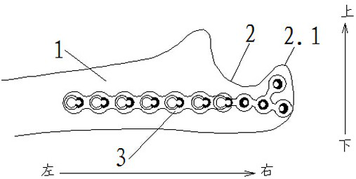
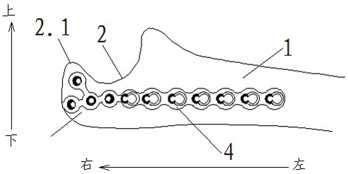
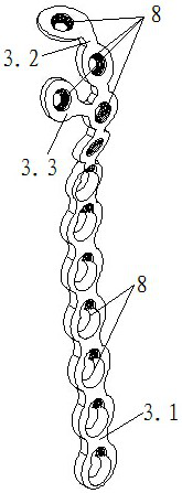
[0055] like Figure 1-4 , as shown in 11-19, an olecranon morphological anatomical locking plate structure, including locking plate I3 and locking plate II4, the locking plate I3 includes a stem I3.1 that can be attached to the front end of the ulnar body 1, and the stem I3.1 is provided with a plurality of locking holes 8, the stem I3.1 is connected with the head I that can fit with the olecranon 2, and the locking plate II4 includes the stem II4 that can fit with the rear end of the ulnar body 1 .1, the stem II 4.1 is provided with a plurality of locking holes 8, and the stem II 4.1 is connected with a head II which can fit with the olecranon 2; Fitted first head I3.2 and second head I3.3 fit to the front end of the olecranon tip 2.1, said head II includes the first head II4 fit to the right end of the olecranon 2 .2 and the second head II 4.3 that can be attached to the rear end of the olecranon tip 2.1; the first head I 3.2 is provided with at least one locking hole 8, th...

Embodiment 2

[0071] like Figure 5-6 As shown, the difference between this embodiment and Embodiment 1 is that the locking hole 8 includes half a tapered threaded hole and half a tapered light hole connected to each other.

Embodiment 3

[0073] like Figure 7-10 As shown, the difference between this embodiment and Embodiment 1-2 is: an anatomical locking plate structure of the olecranon shape, including locking plate I3 and locking plate II4, the locking plate I3 includes a front end that can be connected to the ulnar body 1 Fitted cadre I 3.1, the cadre I 3.1 is provided with a plurality of locking holes 8, the cadre I 3.1 is connected with the head I that can fit with the olecranon 2, and the locking steel plate II 4 includes a The cadre II 4.1 attached to the rear end of the ulnar body 1, the cadre II 4.2 is provided with a plurality of locking holes 8, and the cadre II 4.2 is connected with the head II that can be attached to the olecranon 2; The head I includes a second head I3.3 that can be attached to the front end of the olecranon tip 2.1, and the head II includes a first head II4.2 that can be attached to the right end of the olecranon 2 and can be attached to the front end of the olecranon 2. The se...


PUM


Abstract

The invention relates to an ulna olecranon morphological anatomy locking method and a steel plate structure. The ulna olecranon morphological anatomy locking method comprises the following steps: cutting an ulna body and skin corresponding to olecranon; stripping muscle fascia covering the surfaces of the ulna body and the olecranon and exposing a fracture end and a fracture block; cleaning bloodclots at the fracture end, resetting the fracture block and temporarily fixing the fracture block; observing the reduction condition of the fracture block, placing a locking steel plate II at rear ends of the ulna body and the olecranon, and placing a locking steel plate I at front ends of the ulna body and the olecranon; washing the wound, and confirming the reduction and fixation conditions of the fracture block again; suturing the wound after reduction and fixation of the fracture block meet the requirements. By means of the method, the fracture block can be well fixed, and the arrangementdirection of locking nails and/or leather nails does not point to the concave joint surface and do not enter the joint, so that good safety is achieved.

Description

technical field [0001] The invention relates to the technical field of steel plates used for treating olecranon fractures, in particular to an anatomical locking method for olecranon morphology and a steel plate structure. Background technique [0002] Olecranon fractures are common injuries of the elbow, mostly in adults. The olecranon is curved and protrudes under the skin of the proximal ulna, in the form of an olecranon. The olecranon of the ulna is connected with the coronoid process of the proximal ulna to form a semilunar notch, which becomes a deeply concave articular surface (trochlear notch), and is the hub of elbow flexion and extension. The trochlear notch articulates with the trochlear of the humerus (humero-ulnar joint), a joint that can only move in flexion and extension. Olecranon fractures mostly involve the articular surface of the semilunar notch, which is an intra-articular fracture. Open reduction and internal fixation are required for treatment. The i...

Claims


Application Information

Patent Timeline
Patent Type & Authority Applications(China)
IPC IPC(8): A61B17/80
CPCA61B17/8061A61B17/808A61B2017/00893
Inventor 桑锡光
Owner 桑锡光
Why Eureka
Try Eureka