Cardiac valve prosthesis
A heart valve and prosthesis technology, applied in the field of medical devices, can solve the problems of increasing the difficulty of delivery and the risk of vascular damage, tricuspid valve outflow tract obstruction, poor fatigue resistance, etc., to save crimping space and prevent conduction. The effect of retarding and improving fatigue resistance
- Summary
- Abstract
- Description
- Claims
- Application Information
AI Technical Summary
Problems solved by technology
Method used
Image

Examples
Embodiment 1
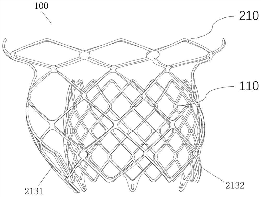
[0055] This embodiment provides a mitral heart valve prosthesis, see Figure 1-Figure 10 , is a schematic diagram of the valve prosthesis of this embodiment, and the valve prosthesis includes a valve and a stent 100 .
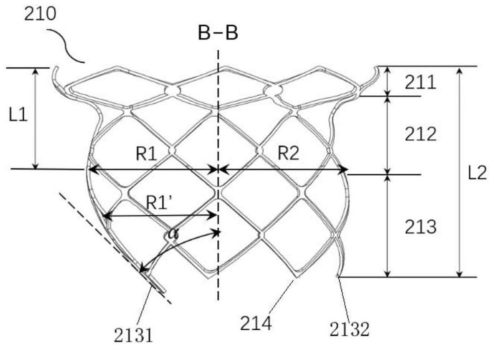
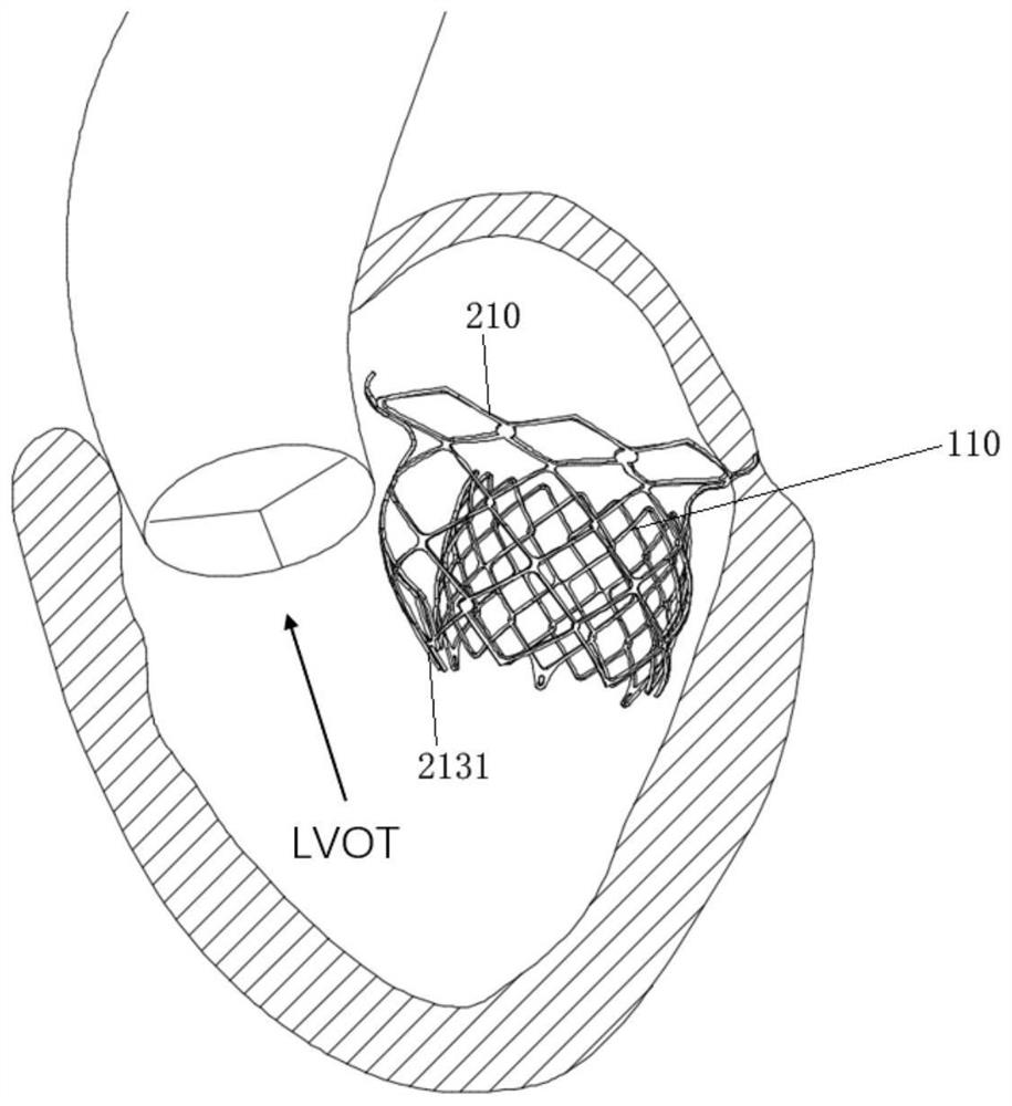
[0056] The stent 100 includes a main body part 110 for supporting the valve and a frame part 210 for fixing the main body part 110, the main body part 110 is connected with the frame part 210; The valve ring segment 212 and the ventricular segment 213 deployed in the ventricle, the valve ring segment 212 is located between the atrial segment 211 and the ventricular segment 213 . The ventricular segment 213 includes a first ventricular segment 2131 and a second ventricular segment 2132 , the first ventricular segment 2131 is located on a side close to the left ventricular outflow tract, and the second ventricular segment 2132 is located on a side far from the left ventricular outflow tract.
[0057] On the side close to the left ventricular outflow tract, the a...
Embodiment 2
[0078] This embodiment provides a valve prosthesis, which is an improvement on the basis of Embodiment 1, wherein the frame part 210 and the main body part 110 are arranged side by side.
[0079] see Figure 11 , is a schematic diagram of the overall structure of the stent 100 of this embodiment, Figure 12 is a schematic perspective view of the stent 100 . Wherein, the main body 110 is a cylinder, the main body 110 is located outside the frame 210 , the outer peripheral side of the frame 210 abuts against the outer peripheral side of the main body 110 , and is connected at the abutment. With such a structure, the frame part 210 and the main body part 110 can produce more connection points, so that the contact area between the frame part 210 and the main body part 110 is larger, so the connection between the two will be more stable; further, the main body part 110 can be maximized. As far as possible away from the left ventricular outflow tract. Moreover, the left and right...
Embodiment 3
[0082] This embodiment provides a valve prosthesis, which is an improvement on the basis of Embodiment 1 or Embodiment 2, wherein the frame part 210 is configured as a non-closed structure.
[0083] Such as Figure 13 As shown, it is a top view of the frame part 210, the frame part 210 is a non-closed structure, and its cross section is semicircular or C-shaped. The non-closed structure can further save the material of the frame part 210, making the valve prosthesis easier to hold and transport.
[0084] Such as Figure 14 As shown, it is a schematic perspective view of the bracket of this embodiment. The frame part 210 and the main body part 110 are side by side structures, wherein the frame part 210 is an opening structure along the axial direction, and the frame part 210 is connected to the main body part at the opening. 110 peripherals are connected.
PUM
| Property | Measurement | Unit |
|---|---|---|
| Outer diameter | aaaaa | aaaaa |
Abstract
Description
Claims
Application Information